Difference between revisions of "ACU Real Time Clock (DIY)"
From CPCWiki - THE Amstrad CPC encyclopedia!
(→Technical) |
(→Article) |
||
| (11 intermediate revisions by 2 users not shown) | |||
| Line 1: | Line 1: | ||
| − | ACU Real Time Clock, DIY from magazine | + | ACU Real Time Clock, DIY from magazine [[Amstrad Computer User|Amstrad User]], April 85. |
| + | |||
| + | * The RTC chip doesn't include a Year register (aside from the leap-year shift register, but it can span only 4 years, and it is write-only). | ||
== Technical == | == Technical == | ||
| − | Uses a Z80 PIO, MM58174 RTC, 6116 ( | + | Uses a [[Z80 PIO]], MM58174 RTC, 6116 (2Kx8bit SRAM), 4040 (12bit counter for sequential SRAM addressing), and 32.768kHz Crystal (for the RTC). Both RTC and RAM are backed by rechargeable 3.6V NiCad battery. Used I/O Ports are (with only A10,A4,A3 decoded): |
| − | + | FBE7h ACU Real Time Clock [[Z80 PIO]] Data In/Out Port A | |
| − | + | Bit7..4 SRAM Data7..4 | |
| − | + | Bit3..0 SRAM Data3..0 and 4bit RTC Data | |
| − | + | FBEFh ACU Real Time Clock [[Z80 PIO]] Data In/Out Port B | |
| + | Bit7 SRAM /CS and /OE (0=Select) | ||
| + | Bit6 RTC /CS (0=Select) | ||
| + | Bit5 RTC /RD (0=Read) | ||
| + | Bit4 RTC /WR (0=Write) | ||
| + | Bit3 RTC Address A3 and SRAM /WE (0=Write) | ||
| + | Bit2 RTC Address A2 and SRAM Address Counter RST (1=Reset, 0=Active) | ||
| + | Bit1 RTC Address A1 | ||
| + | Bit0 RTC Address A0 and SRAM Address Counter /CLK (1-to-0=Increment) | ||
| + | FBF7h ACU Real Time Clock [[Z80 PIO]] Configure Port A | ||
| + | FBFFh ACU Real Time Clock [[Z80 PIO]] Configure Port B | ||
The 4bit RTC Registers are: | The 4bit RTC Registers are: | ||
0 Not used / Test (W) | 0 Not used / Test (W) | ||
| Line 23: | Line 35: | ||
C Month MSB (0..1) (R/W) | C Month MSB (0..1) (R/W) | ||
D Leap Year Shift Register (W) | D Leap Year Shift Register (W) | ||
| − | E Stop/Start (W) | + | E Stop/Start (0=Stop and set Seconds to 00.0, 1=Start) (W) |
F Interrupt (R/W) | F Interrupt (R/W) | ||
| − | Registers 1..C are BCD (range 0..9), a value of 0Fh in these registers indicates Failure | + | Registers 1..C are BCD (range 0..9), a value of 0Fh in these registers indicates Failure (this may happen if the time changed while reading - if that happens, restart reading ALL time registers). |
| − | + | ||
== Article == | == Article == | ||
| − | <gallery> | + | <gallery caption="Part 1 - RTC DIY Hardware (ACU April 1985)"> |
image:Amstrad Computer User8504 078.jpg | image:Amstrad Computer User8504 078.jpg | ||
image:Amstrad Computer User8504 079.jpg | image:Amstrad Computer User8504 079.jpg | ||
| Line 37: | Line 48: | ||
</gallery> | </gallery> | ||
| − | + | Observe that the part number, MM58147, in the headline is wrong (it's meant to be MM58174). | |
| + | |||
| + | <gallery caption="Part 2 - Software for the RTC (ACU May 1985)"> | ||
| + | image:ACU8505-008.jpg | ||
| + | image:ACU8505-014.jpg | ||
| + | image:ACU8505-016.jpg | ||
| + | </gallery> | ||
| + | [[Category:Peripherals]] [[Category:DIY]] | ||
Latest revision as of 20:11, 6 April 2012
ACU Real Time Clock, DIY from magazine Amstrad User, April 85.
- The RTC chip doesn't include a Year register (aside from the leap-year shift register, but it can span only 4 years, and it is write-only).
Technical
Uses a Z80 PIO, MM58174 RTC, 6116 (2Kx8bit SRAM), 4040 (12bit counter for sequential SRAM addressing), and 32.768kHz Crystal (for the RTC). Both RTC and RAM are backed by rechargeable 3.6V NiCad battery. Used I/O Ports are (with only A10,A4,A3 decoded):
 FBE7h  ACU Real Time Clock Z80 PIO Data In/Out Port A
             Bit7..4  SRAM Data7..4
             Bit3..0  SRAM Data3..0 and 4bit RTC Data
 FBEFh  ACU Real Time Clock Z80 PIO Data In/Out Port B
             Bit7     SRAM /CS and /OE (0=Select)
             Bit6     RTC /CS (0=Select)
             Bit5     RTC /RD (0=Read)
             Bit4     RTC /WR (0=Write)
             Bit3     RTC Address A3 and SRAM /WE (0=Write)
             Bit2     RTC Address A2 and SRAM Address Counter RST (1=Reset, 0=Active)
             Bit1     RTC Address A1
             Bit0     RTC Address A0 and SRAM Address Counter /CLK (1-to-0=Increment)
 FBF7h  ACU Real Time Clock Z80 PIO Configure Port A
 FBFFh  ACU Real Time Clock Z80 PIO Configure Port B
The 4bit RTC Registers are:
 0  Not used / Test (W)
 1  Seconds 1/10s Fraction (0..9) (R)
 2  Seconds LSB (0..9) (R)
 3  Seconds MSB (0..5) (R)
 4  Minutes LSB (0..9) (R/W)
 5  Minutes MSB (0..5) (R/W)
 6  Hours LSB (0..9) (R/W)
 7  Hours MSB (0..2) (R/W)
 8  Day LSB (0..9) (R/W)
 9  Day MSB (0..3) (R/W)
 A  Day of Week (1..7) (R/W)
 B  Month LSB (0..9) (R/W)
 C  Month MSB (0..1) (R/W)
 D  Leap Year Shift Register (W)
 E  Stop/Start (0=Stop and set Seconds to 00.0, 1=Start) (W)
 F  Interrupt (R/W)
Registers 1..C are BCD (range 0..9), a value of 0Fh in these registers indicates Failure (this may happen if the time changed while reading - if that happens, restart reading ALL time registers).
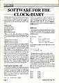
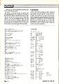
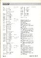
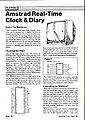
Article
- Part 1 - RTC DIY Hardware (ACU April 1985)
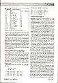
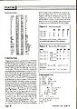
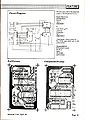


Observe that the part number, MM58147, in the headline is wrong (it's meant to be MM58174).
- Part 2 - Software for the RTC (ACU May 1985)