Difference between revisions of "Amstrad FDD part"
(Created page with "Amstrad used different floppy disk drives during the CPC range live time. These drives where either build-in as in CPC6128 and CPC464 or within the [[Amstrad_Disk_Drive|DDI-1/...") |
(→EME-156) |
||
| (6 intermediate revisions by one other user not shown) | |||
| Line 37: | Line 37: | ||
* Insertion mechanism simplification. The floppy now rotate around the insertion slot toward the floppy drive mechanism. The external visual impact is a slimmer insertion slot. | * Insertion mechanism simplification. The floppy now rotate around the insertion slot toward the floppy drive mechanism. The external visual impact is a slimmer insertion slot. | ||
* Index detection led uses a small PCB mounted on the loading mechanism. | * Index detection led uses a small PCB mounted on the loading mechanism. | ||
| − | * <span style="color:#FF0000">The write protection sensing is done using a switch / pin assembly.</span> | + | * <span style="color:#FF0000">The write protection sensing is done using a [[Writepin|switch / pin assembly]].</span> |
<div style="clear: both"></div> | <div style="clear: both"></div> | ||
| + | |||
| + | The Test Points under the PCB are found near the front of the drive, near the drive LED. | ||
| + | |||
| + | On the 5 pin TP connector: | ||
| + | |||
| + | * pin 1 or pin 2 for head amplifier | ||
| + | * pin 3 is GND | ||
| + | * pin 4 is the index hole detection (high on index) | ||
| + | * pin 5 for track0 sensor (low when on track 0) | ||
| + | |||
| + | Reference: https://www.cpcwiki.eu/forum/amstrad-cpc-hardware/eme-156-mechanics/msg172359/#msg172359 | ||
=== EME-156 V === | === EME-156 V === | ||
| Line 47: | Line 58: | ||
* New head motor with a smaller diameter screw. | * New head motor with a smaller diameter screw. | ||
* Main PCB (Z80264) is 50% smaller than previous version. It cannot be fully removed without de-soldering some wires or un-mounting index sensor and track 0 sensor. Track 0 sensor has to be calibrated when mounted. | * Main PCB (Z80264) is 50% smaller than previous version. It cannot be fully removed without de-soldering some wires or un-mounting index sensor and track 0 sensor. Track 0 sensor has to be calibrated when mounted. | ||
| − | * <span style="color:#FF0000">The write protection sensing is done using a switch / pin assembly.</span> | + | * <span style="color:#FF0000">The write protection sensing is done using a [[Writepin|switch / pin assembly]].</span> |
<div style="clear: both"></div> | <div style="clear: both"></div> | ||
| Line 55: | Line 66: | ||
* Head and drive motors changed for 5V version. | * Head and drive motors changed for 5V version. | ||
* Main PCB (Z80425) slightly smaller than EME-156 V one. It cannot be fully removed without de-soldering some wires or un-mounting index sensor and track 0 sensor. Track 0 sensor has to be calibrated when mounted. | * Main PCB (Z80425) slightly smaller than EME-156 V one. It cannot be fully removed without de-soldering some wires or un-mounting index sensor and track 0 sensor. Track 0 sensor has to be calibrated when mounted. | ||
| − | * White face to match Plus range | + | * White face to match Plus range colour. |
* Minor modification of the brass chassis near the drive motor | * Minor modification of the brass chassis near the drive motor | ||
| − | * <span style="color:#FF0000">The write protection sensing is done using a switch / pin assembly.</span> | + | * <span style="color:#FF0000">The write protection sensing is done using a [[Writepin|switch / pin assembly]].</span> |
<div style="clear: both"></div> | <div style="clear: both"></div> | ||
| + | |||
| + | == Drive maintenance == | ||
| + | === Rotation speed adjustment === | ||
| + | 3 inch drive spins at 300 RPM, giving a 200ms index pulse period. Rotation speed is factory adjusted, but may drift with time and cause read problem when drift is too large. | ||
| + | |||
| + | On EME 150A, the drive motor speed regulation is done on the main unit PCB, and is adjusted using VR201. | ||
| + | On Other model (155/156/156V/157), the drive motor includes its own regulation PCB, and adjustment is done on the motor itself, which can be one of the following reference (MMA-xxxxxx, QJN2-xxxx or MMU-xxxxxx) | ||
| + | <gallery> | ||
| + | File:EME-150A_RpmAdjust.jpg|EME-150 A speed adjust | ||
| + | File:EME-156_RpmAdjust.jpg|EME-156 A speed adjust | ||
| + | File:MMU-5B2LQJ_open.JPG|Detail of MMU-5B2LQJ motor speed regulator | ||
| + | </gallery> | ||
| + | |||
| + | Rotation speed can be checked either by monitoring the drive index pulse with an oscilloscope or by using dedicated SW like [http://www.cpcwiki.eu/forum/applications/dsktest-v0-1b/ DskTest] or [http://www.amstradtoday.com/resur/rpm.zip RPM]. | ||
| + | |||
| + | Adjustment requires a 2mm wide screwdriver. A larger one will not fit in the potentiometer adjustment hole. | ||
| + | |||
| + | On MMA-xxxxxx, the adjustment hole is covered with a white rubber and the internal PCB is facing down. <span style="color:#FF0000">That requires additional precautions : forcing the screwdriver in the hole may detach the potentiometer from the PCB and damage the motor.</span> | ||
| + | |||
| + | On QJN2-xxxx and MMU-xxxxxx, the adjustment hole is covered with a black rubber and the internal PCB is facing up. | ||
== Gallery == | == Gallery == | ||
| Line 87: | Line 118: | ||
File:EME-156 Right.jpg|EME-156 Right side | File:EME-156 Right.jpg|EME-156 Right side | ||
File:EME-156 Left.jpg|EME-156 Left side | File:EME-156 Left.jpg|EME-156 Left side | ||
| − | File:EME-156 Bottom.jpg|EME-156 Bottom | + | File:EME-156 Bottom.jpg|EME-156 Bottom ME56PB31 PCB |
| + | File:EME-156 Bottom ME56PB41.png|EME-156 Bottom ME56PB41 PCB | ||
</gallery> | </gallery> | ||
| Line 107: | Line 139: | ||
File:EME-157 Bottom.jpg|EME-157 Bottom | File:EME-157 Bottom.jpg|EME-157 Bottom | ||
</gallery> | </gallery> | ||
| + | |||
| + | [[Category:DATA Storage]][[Category:CPC Internal Components]][[Category:DATA Storage]][[Category:Hardware]] | ||
Latest revision as of 02:53, 5 December 2020
Amstrad used different floppy disk drives during the CPC range live time. These drives where either build-in as in CPC6128 and CPC464 or within the DDI-1/FD-1 external drive extension.
They all shared the following characteristics :
- Requires 5V and 12V power supply, except EME-157 which is 5V only.
- use CF2 Compact Floppy Disc 3" discs
- Single sided
- 40 tracks
- 180kB per side (40 tracks/9 512byte sector per track)
Contents
Floppy disk models and evolution
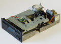
EME-150 A

Manufactured by matsushita, this is the original drive used in CPC664 and early DDI1 / CPC6128. Used from 1984 to early 1985.
- The chassis is made of one brass aluminium piece on which the disk axis, drive motor, head motor, track 0 detector and head assembly are precisely mounted.
- This base is mounted on a folded sheet chassis that support the disk insertion mechanism and a PCB holding the LED for index and write protection sensing as well as connection to track 0 detector.
- The insertion mechanism is working by translation of the floppy on the drive mechanism.
- Main PCB (30001) can be fully removed to access drive belt.
EME-155

Evolution of the EME-150 A, used during 1985.
- Head and floppy motor reference changed and swapped they position. Now the head motor is on the right, the drive one on the left.
- Due to the motor swap, the top PCB only support the index and write protection detection led.
- Main PCB (30002) can be fully removed to access drive belt.
- The optical write protection sensor use a new reference.
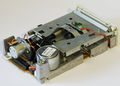
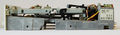
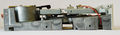
EME-156

New design, used from 1986 to 1988
- Uses EME-155 head and drive motors.
- Full brass aluminium chassis.
- New head.
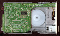
- Main PCB (Z70312) cannot be fully removed without de-soldering some wires or un-mounting index sensor and track 0 sensor. Track 0 sensor has to be calibrated when mounted.
- Insertion mechanism simplification. The floppy now rotate around the insertion slot toward the floppy drive mechanism. The external visual impact is a slimmer insertion slot.
- Index detection led uses a small PCB mounted on the loading mechanism.
- The write protection sensing is done using a switch / pin assembly.
The Test Points under the PCB are found near the front of the drive, near the drive LED.
On the 5 pin TP connector:
- pin 1 or pin 2 for head amplifier
- pin 3 is GND
- pin 4 is the index hole detection (high on index)
- pin 5 for track0 sensor (low when on track 0)
Reference: https://www.cpcwiki.eu/forum/amstrad-cpc-hardware/eme-156-mechanics/msg172359/#msg172359
EME-156 V

Cost optimised version of the EME-156, used from mid 1988
- Brass aluminium chassis has been trimmed of unnecessary bits.
- Floppy drive mechanism pulley is changed for a lighter one with a increased diameter. The floppy motor position is slightly moved inward to compensate for the new pulley diameter and keep identical belt.
- New head motor with a smaller diameter screw.
- Main PCB (Z80264) is 50% smaller than previous version. It cannot be fully removed without de-soldering some wires or un-mounting index sensor and track 0 sensor. Track 0 sensor has to be calibrated when mounted.
- The write protection sensing is done using a switch / pin assembly.
EME-157

5 volt only version of EME-156 V. Used in the 6128 plus.
- Head and drive motors changed for 5V version.
- Main PCB (Z80425) slightly smaller than EME-156 V one. It cannot be fully removed without de-soldering some wires or un-mounting index sensor and track 0 sensor. Track 0 sensor has to be calibrated when mounted.
- White face to match Plus range colour.
- Minor modification of the brass chassis near the drive motor
- The write protection sensing is done using a switch / pin assembly.
Drive maintenance
Rotation speed adjustment
3 inch drive spins at 300 RPM, giving a 200ms index pulse period. Rotation speed is factory adjusted, but may drift with time and cause read problem when drift is too large.
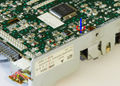
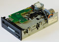
On EME 150A, the drive motor speed regulation is done on the main unit PCB, and is adjusted using VR201. On Other model (155/156/156V/157), the drive motor includes its own regulation PCB, and adjustment is done on the motor itself, which can be one of the following reference (MMA-xxxxxx, QJN2-xxxx or MMU-xxxxxx)
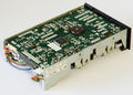
EME-150 A speed adjust

EME-156 A speed adjust
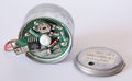
Detail of MMU-5B2LQJ motor speed regulator


Rotation speed can be checked either by monitoring the drive index pulse with an oscilloscope or by using dedicated SW like DskTest or RPM.
Adjustment requires a 2mm wide screwdriver. A larger one will not fit in the potentiometer adjustment hole.
On MMA-xxxxxx, the adjustment hole is covered with a white rubber and the internal PCB is facing down. That requires additional precautions : forcing the screwdriver in the hole may detach the potentiometer from the PCB and damage the motor.
On QJN2-xxxx and MMU-xxxxxx, the adjustment hole is covered with a black rubber and the internal PCB is facing up.
Gallery
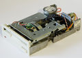
EME-150 A Front/Right

EME-150 A Back/Left
EME-150 A Back/Right

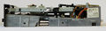
EME-150 A Right side
EME-150 A Left side
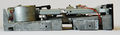
EME-150 A Bottom

EME-150 A PCB top


EME-155 Front/Right

EME-155 Back/Left

EME-155 Back/Right
EME-155 Right side

EME-155 Left side

EME-155 Bottom

EME-155 PCB top


EME-156 Front/Right

EME-156 Back/Left
EME-156 Back/Right
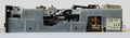
EME-156 Right side
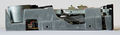
EME-156 Left side

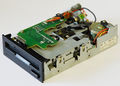
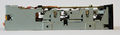
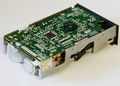
EME-156 Bottom ME56PB31 PCB
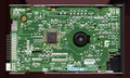
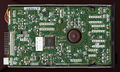
EME-156 Bottom ME56PB41 PCB


EME-156 V Front/Right

EME-156 V Back/Left

EME-156 V Back/Right
EME-156 V Right side
EME-156 V Left side

EME-156 V Bottom


EME-157 Front/Right
EME-157 Back/Left

EME-157 Back/Right
EME-157 Right side
EME-157 Left side
EME-157 Bottom


