Difference between revisions of "Amstrad FDD part"
(Created page with "Amstrad used different floppy disk drives during the CPC range live time. These drives where either build-in as in CPC6128 and CPC464 or within the [[Amstrad_Disk_Drive|DDI-1/...") |
m |
||
| Line 107: | Line 107: | ||
File:EME-157 Bottom.jpg|EME-157 Bottom | File:EME-157 Bottom.jpg|EME-157 Bottom | ||
</gallery> | </gallery> | ||
| + | |||
| + | [[Category:DATA Storage]][[Category:CPC Internal Components]][[Category:DATA Storage]][[Category:Hardware]] | ||
Revision as of 09:03, 12 February 2014
Amstrad used different floppy disk drives during the CPC range live time. These drives where either build-in as in CPC6128 and CPC464 or within the DDI-1/FD-1 external drive extension.
They all shared the following characteristics :
- Requires 5V and 12V power supply, except EME-157 which is 5V only.
- use CF2 Compact Floppy Disc 3" discs
- Single sided
- 40 tracks
- 180kB per side (40 tracks/9 512byte sector per track)
Contents
Floppy disk models and evolution
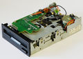
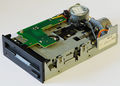
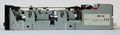
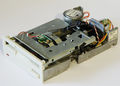
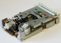
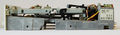
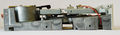
EME-150 A

Manufactured by matsushita, this is the original drive used in CPC664 and early DDI1 / CPC6128. Used from 1984 to early 1985.
- The chassis is made of one brass aluminium piece on which the disk axis, drive motor, head motor, track 0 detector and head assembly are precisely mounted.
- This base is mounted on a folded sheet chassis that support the disk insertion mechanism and a PCB holding the LED for index and write protection sensing as well as connection to track 0 detector.
- The insertion mechanism is working by translation of the floppy on the drive mechanism.
- Main PCB (30001) can be fully removed to access drive belt.
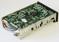
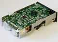
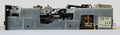
EME-155

Evolution of the EME-150 A, used during 1985.
- Head and floppy motor reference changed and swapped they position. Now the head motor is on the right, the drive one on the left.
- Due to the motor swap, the top PCB only support the index and write protection detection led.
- Main PCB (30002) can be fully removed to access drive belt.
- The optical write protection sensor use a new reference.
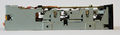
EME-156

New design, used from 1986 to 1988
- Uses EME-155 head and drive motors.
- Full brass aluminium chassis.
- New head.
- Main PCB (Z70312) cannot be fully removed without de-soldering some wires or un-mounting index sensor and track 0 sensor. Track 0 sensor has to be calibrated when mounted.
- Insertion mechanism simplification. The floppy now rotate around the insertion slot toward the floppy drive mechanism. The external visual impact is a slimmer insertion slot.
- Index detection led uses a small PCB mounted on the loading mechanism.
- The write protection sensing is done using a switch / pin assembly.
EME-156 V

Cost optimised version of the EME-156, used from mid 1988
- Brass aluminium chassis has been trimmed of unnecessary bits.
- Floppy drive mechanism pulley is changed for a lighter one with a increased diameter. The floppy motor position is slightly moved inward to compensate for the new pulley diameter and keep identical belt.
- New head motor with a smaller diameter screw.
- Main PCB (Z80264) is 50% smaller than previous version. It cannot be fully removed without de-soldering some wires or un-mounting index sensor and track 0 sensor. Track 0 sensor has to be calibrated when mounted.
- The write protection sensing is done using a switch / pin assembly.
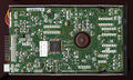
EME-157

5 volt only version of EME-156 V. Used in the 6128 plus.
- Head and drive motors changed for 5V version.
- Main PCB (Z80425) slightly smaller than EME-156 V one. It cannot be fully removed without de-soldering some wires or un-mounting index sensor and track 0 sensor. Track 0 sensor has to be calibrated when mounted.
- White face to match Plus range coulor.
- Minor modification of the brass chassis near the drive motor
- The write protection sensing is done using a switch / pin assembly.
Gallery
EME-150 A Front/Right

EME-150 A Back/Left
EME-150 A Back/Right

EME-150 A Right side
EME-150 A Left side
EME-150 A Bottom

EME-150 A PCB top


EME-155 Front/Right

EME-155 Back/Left

EME-155 Back/Right
EME-155 Right side

EME-155 Left side

EME-155 Bottom

EME-155 PCB top


EME-156 Front/Right

EME-156 Back/Left
EME-156 Back/Right
EME-156 Right side
EME-156 Left side

EME-156 Bottom


EME-156 V Front/Right

EME-156 V Back/Left

EME-156 V Back/Right
EME-156 V Right side
EME-156 V Left side

EME-156 V Bottom


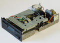
EME-157 Front/Right
EME-157 Back/Left

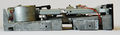
EME-157 Back/Right
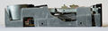
EME-157 Right side
EME-157 Left side
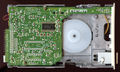
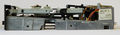
EME-157 Bottom


