Difference between revisions of "Amstrad Whole Memory Guide - General system arrangement"
m (→The I/O Map) |
(Added page 5; still some missing links in references to other sections.) |
||
| (3 intermediate revisions by 2 users not shown) | |||
| Line 3: | Line 3: | ||
== GENERAL SYSTEM ARRANGEMENT == | == GENERAL SYSTEM ARRANGEMENT == | ||
| − | Superficially, the CPC464 is a typical | + | Superficially, the CPC464 is a typical Z80—based system, with an unusually economical arrangement of peripheral devices. By making full use of the capabilities of these devices, a performance level has been obtained which is higher than the limited chip count might suggest. One consequence of this is that the operating system is especially complex, a fact which is offset by the comparative ease of user access to the various functions. The word ‘comparative‘ is necessary, because knowledge of machine code is needed, which may be a difficulty for some users, but once they have come to terms with machine code a wide range of possibilities opens up. |
Among other ingenuities, the way in which a minimum of 96K of memory has been packed into a 64K memory map is especially noteworthy, and this aspect of the system will be studied first. | Among other ingenuities, the way in which a minimum of 96K of memory has been packed into a 64K memory map is especially noteworthy, and this aspect of the system will be studied first. | ||
| Line 9: | Line 9: | ||
=== The Memory Map === | === The Memory Map === | ||
| − | The whole of the 64K byte memory is occupied by RAM, to which any writes to memory will be directed. This makes sense, since there is | + | The whole of the 64K byte memory is occupied by RAM, to which any writes to memory will be directed. This makes sense, since there is no point in trying to write to ROM. Reads from addresses in the middle half of memory will also access RAM, there being no ROM in this area. For addresses in the top and bottom quarters of memory, however, both ROM and RAN are present, and it is possible to read from either at will. A BASIC peek will always access RAM, so a special bit of machine code is needed to obtain the contents of ROM. |
| − | The memory arrangement is complicated by the fact that the top quarter of RAM is dedicated to use as screen memory, and | + | The memory arrangement is complicated by the fact that the top quarter of RAM is dedicated to use as screen memory, and must be immediately accessible at regular intervals while data Is being passed to the display. For this purpose, two bytes are read every microsecond. |
The processor is put into a wait state while the pairs of bytes are being transferred, the transfer being made directly from memory to the Video Gate Array, using an address generated by the CRT Controller chip. This means that the main processor can only make one memory access per microsecond, and although its clock runs at 4 MHz the actual processing speed is slightly reduced, a point to watch when calculating execution times. | The processor is put into a wait state while the pairs of bytes are being transferred, the transfer being made directly from memory to the Video Gate Array, using an address generated by the CRT Controller chip. This means that the main processor can only make one memory access per microsecond, and although its clock runs at 4 MHz the actual processing speed is slightly reduced, a point to watch when calculating execution times. | ||
| Line 31: | Line 31: | ||
* If address bit A14 is low, the CRT Controller is selected. Address bits A8 and A9 are used to select four different transfer modes: | * If address bit A14 is low, the CRT Controller is selected. Address bits A8 and A9 are used to select four different transfer modes: | ||
| − | BCXX Output to Register Select | + | {| class="wikitable" |
| − | BDXX Data Output | + | |- |
| − | BEXX Status Input | + | | BCXX || Output to Register Select |
| − | BFXX Data Input | + | |- |
| + | | BDXX || Data Output | ||
| + | |- | ||
| + | | BEXX || Status Input | ||
| + | |- | ||
| + | | BFXX || Data Input | ||
| + | |} | ||
* If address bit A13 is low, ROM select data is being output. The address must be DFXX. | * If address bit A13 is low, ROM select data is being output. The address must be DFXX. | ||
| Line 42: | Line 48: | ||
* If address bit A11 is low, the Parallel Peripheral Interface (PPI) is selected. Here again, bits A8 and A9 are used to select four sub—channels: | * If address bit A11 is low, the Parallel Peripheral Interface (PPI) is selected. Here again, bits A8 and A9 are used to select four sub—channels: | ||
| − | F4XX Port A (I/O) | + | {| class="wikitable" |
| − | F5XX Port B (I/O) | + | |- |
| − | F6XX | + | | F4XX || Port A (I/O) |
| − | F7XX Control (Output only) | + | |- |
| + | | F5XX || Port B (I/O) | ||
| + | |- | ||
| + | | F6XX || Port C (I/O) | ||
| + | |- | ||
| + | | F7XX || Control (Output only) | ||
| + | |} | ||
* If address bit A10 is low, an expansion channel is selected. In this case, bits A5 — A7 have special significance: | * If address bit A10 is low, an expansion channel is selected. In this case, bits A5 — A7 have special significance: | ||
| − | + | ** A5 low selects a communication channel. | |
| − | A5 low selects a communication channel. | + | ** A6 low selects a reserved function. |
| − | A6 low selects a reserved function. | + | ** A7 low selects the disc System. |
| − | A7 low selects the disc System. | + | |
* Address F8FF is a general reset for expansion channels. | * Address F8FF is a general reset for expansion channels. | ||
| Line 61: | Line 72: | ||
=== Outer Peripherals === | === Outer Peripherals === | ||
| − | The devices mentioned above are the ‘inner peripherals‘, which are accessed directly from the main processor. Further devices, classed as the ‘Outer Peripherals‘, are accessed by the inner peripherals. They include the Programmable Sound Generator, | + | The devices mentioned above are the ‘inner peripherals‘, which are accessed directly from the main processor. Further devices, classed as the ‘Outer Peripherals‘, are accessed by the inner peripherals. They include the Programmable Sound Generator, accessed by the PPI; the keyboard, accessed by the PPI and the Sound Generator; the Cassette Recorder, accessed by the PPI; the Loudspeaker, driven by the Sound Generator. |
| − | + | ||
| − | Sound Generator; the Cassette Recorder, accessed by the PPI; the Loudspeaker, driven by the Sound Generator. | + | |
For further details of the hardware system, consult ‘[[The Ins & Outs of the Amstrad|The Ins and Outs of the Amstrad]]‘, which gives additional Information on the coding and action of these devices. | For further details of the hardware system, consult ‘[[The Ins & Outs of the Amstrad|The Ins and Outs of the Amstrad]]‘, which gives additional Information on the coding and action of these devices. | ||
| Line 69: | Line 78: | ||
=== System States === | === System States === | ||
| − | At switch-on, a number of initialisation procedures are executed, and control then passes to upper ROM | + | At switch-on, a number of initialisation procedures are executed, and control then passes to upper ROM 0. If there is no external ROM of this number, the internal BASIC interpreter takes charge as the ‘foreground‘ program. |
Once a foreground program has been entered, it remains in charge until a return at entry level is executed, when a full reset is performed, and ROM is again put in charge. However, the foreground program can call on background programs for assistance, and these, in turn, can call other programs. There is thus — nominally — one foreground level, but there can be several background levels. | Once a foreground program has been entered, it remains in charge until a return at entry level is executed, when a full reset is performed, and ROM is again put in charge. However, the foreground program can call on background programs for assistance, and these, in turn, can call other programs. There is thus — nominally — one foreground level, but there can be several background levels. | ||
| Line 75: | Line 84: | ||
A ROM other than 0, or a program in RAM, can be selected as the foreground program. This can be done by a RUN”” command which reads a machine code program that has a defined Start address, or by a machine code routine. It may be more convenient to leave the BASIC interpreter nominally in charge and run a program CALLed from BASIC as if it was a foreground program. This has the advantage that a full reset is not inevitable in response to a return at entry level. Instead, the interpreter is re—entered. | A ROM other than 0, or a program in RAM, can be selected as the foreground program. This can be done by a RUN”” command which reads a machine code program that has a defined Start address, or by a machine code routine. It may be more convenient to leave the BASIC interpreter nominally in charge and run a program CALLed from BASIC as if it was a foreground program. This has the advantage that a full reset is not inevitable in response to a return at entry level. Instead, the interpreter is re—entered. | ||
| − | Using BASIC in this way has other advantages. [[HIMEM]] can be checked and adjusted quite easy putting it below the area in which machine code is to reside, and other system variables can be set up. The BASIC program will use some RAM, particularly from | + | Using BASIC in this way has other advantages. [[HIMEM]] can be checked and adjusted quite easy putting it below the area in which machine code is to reside, and other system variables can be set up. The BASIC program will use some RAM, particularly from 0170 upwards, but this is likely to be a negligible drain on the large RAM area available. |
One point to watch is that if extension systems are added, such as disc drive, speech facility, or the [[Maxam|MAXAM]] assembler in ROM form, HIMEM is lowered, because the extensions have claimed workspace for their own use. Some commercial programs are incompatible with a disc drive ‚ because they trespass on the disc workspace. Protected or not, they cannot be transferred to disc. | One point to watch is that if extension systems are added, such as disc drive, speech facility, or the [[Maxam|MAXAM]] assembler in ROM form, HIMEM is lowered, because the extensions have claimed workspace for their own use. Some commercial programs are incompatible with a disc drive ‚ because they trespass on the disc workspace. Protected or not, they cannot be transferred to disc. | ||
| Line 81: | Line 90: | ||
As a guide, HIMEM is AB7F in typical circumstances, but drops to A67B with disc drives connected, and may go even lower with [[AMSDOS]] active. | As a guide, HIMEM is AB7F in typical circumstances, but drops to A67B with disc drives connected, and may go even lower with [[AMSDOS]] active. | ||
| + | The official advice is that machine code programs should be relocatable, but that is not always feasible. It has been noted, however, that it is possible to set short routines in the BF00 area, and these survive a reset, which is useful ... | ||
| + | |||
| + | === Jumpblock Entries === | ||
| + | |||
| + | The RAM area from BB00 to BDC9 holds instructions accessing the principal operating system entries. Special jumps are used which select the required ROM automatically. Entries beginning &CF do this and no more, but entries beginning &EF also disable the relevant ROM when the routine returns. (See the section on 'The HST Area'.) | ||
| + | |||
| + | The jumpblock entries should be accessed by subroutine calls, so that a return address is available on the stack. | ||
| + | |||
| + | From BDCD to BDF3 the entries are simple jumps, beginning &C3. These are ‘indirections', which do not enable the appropriate ROM and should only be called when it is known that the ROM is already selected. | ||
| + | |||
| + | The intention is that the jumpblock addresses should not change, though they may access different entry points with different system versions. However, for ease of reference each routine description is headed by the jumpblock address and the associated destination in the operating system. The latter will | ||
| + | change with the system version, as in the CPC664, and the new entry points must be determined by checking the jumpblock | ||
| + | instructions. | ||
| + | |||
| + | === Summary === | ||
| + | |||
| + | This quick tour of the main system features should have served as a useful introduction to the system. We must now begin to look more closely at detail, beginning with the routines held in RAM. | ||
| + | |||
| + | === Conventions === | ||
| + | |||
| + | Two—digit hexadecimal numbers will are prefaced by '&', four—digit hexadecimal numbers are not. Brackets round a four—digit number indicate the contents of the location at the address identified by the number. Where the brackets contain a range of numbers, e.g in the form (00FA/D), the joint contents of the locations specified are indicated. | ||
== Scanned pages == | == Scanned pages == | ||
Latest revision as of 19:26, 18 February 2018
Chapter 1 in the book Amstrad Whole Memory Guide.
Contents
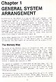
GENERAL SYSTEM ARRANGEMENT
Superficially, the CPC464 is a typical Z80—based system, with an unusually economical arrangement of peripheral devices. By making full use of the capabilities of these devices, a performance level has been obtained which is higher than the limited chip count might suggest. One consequence of this is that the operating system is especially complex, a fact which is offset by the comparative ease of user access to the various functions. The word ‘comparative‘ is necessary, because knowledge of machine code is needed, which may be a difficulty for some users, but once they have come to terms with machine code a wide range of possibilities opens up.
Among other ingenuities, the way in which a minimum of 96K of memory has been packed into a 64K memory map is especially noteworthy, and this aspect of the system will be studied first.
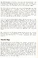
The Memory Map
The whole of the 64K byte memory is occupied by RAM, to which any writes to memory will be directed. This makes sense, since there is no point in trying to write to ROM. Reads from addresses in the middle half of memory will also access RAM, there being no ROM in this area. For addresses in the top and bottom quarters of memory, however, both ROM and RAN are present, and it is possible to read from either at will. A BASIC peek will always access RAM, so a special bit of machine code is needed to obtain the contents of ROM.
The memory arrangement is complicated by the fact that the top quarter of RAM is dedicated to use as screen memory, and must be immediately accessible at regular intervals while data Is being passed to the display. For this purpose, two bytes are read every microsecond.
The processor is put into a wait state while the pairs of bytes are being transferred, the transfer being made directly from memory to the Video Gate Array, using an address generated by the CRT Controller chip. This means that the main processor can only make one memory access per microsecond, and although its clock runs at 4 MHz the actual processing speed is slightly reduced, a point to watch when calculating execution times.
The Video Gate Array handles the switching between ROM and RAM for this purpose, so it is natural that it is also used to control ROM selection in general. The instructions for switching between ROM and RAM are given by outputs to bits 2 and 3 of port 7FXX. A 1 disables, a 0 enables, while bit 2 applies to the lower ROM and bit 3 to the upper ROM. Incidentally, there is only one ROM component, some address fiddling dividing it into two 16K blocks as far as the System is concerned.
As in any bank-switching memory system, the key problem is the need to jump and switch banks simultaneously, or to appear to do so. The CPC464 achieves this by using routines held in central RAM. These are always accessible, whatever the ROM selection state. In addition to simple switching between ROM and RAM, these routines allow the selection of alternative upper ROMs, extending the available memory still further. In the extreme, it would nominally be possible to address a total of 4128K bytes of memory, but few systems are likely to approach that ultimate limit.
The complexities of the memory System can be evaded by putting machine code into the central half of the memory map, which contains only RAM, but this is neither essential nor always feasible.
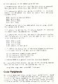
The I/O Map
The selection of peripheral channels is largely determined by making one of the bits of the upper byte of the 16—bit I/O address low, which means that the older I/O instructions of the form IN A,(N) and OUT (N),A cannot be used, because they draw the upper byte from the contents of the A register. Instructions which set the I/O address from the contents of the BC register are mandatory, and there are strict limits regarding the contents of the B register, because no more than one of the six upper bits may be low in any given address. (Making more than one of these bits low in an input instruction invites physical damage, because two data sources may fight for control of the bus, while it is rarely sensible to send the same output to two different ports at the same time.)
The I/O addresses can be summed up as follows:
- If address bit A15 is low, the Video Gate Array is selected. This port is for output only. The address must be 7FXX.
- If address bit A14 is low, the CRT Controller is selected. Address bits A8 and A9 are used to select four different transfer modes:
| BCXX | Output to Register Select |
| BDXX | Data Output |
| BEXX | Status Input |
| BFXX | Data Input |
- If address bit A13 is low, ROM select data is being output. The address must be DFXX.
- If address bit A12 is low, the printer channel is selected for output only. The address must be EFXX.
- If address bit A11 is low, the Parallel Peripheral Interface (PPI) is selected. Here again, bits A8 and A9 are used to select four sub—channels:
| F4XX | Port A (I/O) |
| F5XX | Port B (I/O) |
| F6XX | Port C (I/O) |
| F7XX | Control (Output only) |
- If address bit A10 is low, an expansion channel is selected. In this case, bits A5 — A7 have special significance:
- A5 low selects a communication channel.
- A6 low selects a reserved function.
- A7 low selects the disc System.
- Address F8FF is a general reset for expansion channels.
The above allocations restrict the user to the following address ranges for any special I/O functions he may require:
F8E0—F8FE: F9E0—F9FF: FAE0—FAFF: FBE0—FBFF
Outer Peripherals
The devices mentioned above are the ‘inner peripherals‘, which are accessed directly from the main processor. Further devices, classed as the ‘Outer Peripherals‘, are accessed by the inner peripherals. They include the Programmable Sound Generator, accessed by the PPI; the keyboard, accessed by the PPI and the Sound Generator; the Cassette Recorder, accessed by the PPI; the Loudspeaker, driven by the Sound Generator.
For further details of the hardware system, consult ‘The Ins and Outs of the Amstrad‘, which gives additional Information on the coding and action of these devices.
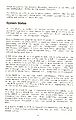
System States
At switch-on, a number of initialisation procedures are executed, and control then passes to upper ROM 0. If there is no external ROM of this number, the internal BASIC interpreter takes charge as the ‘foreground‘ program.
Once a foreground program has been entered, it remains in charge until a return at entry level is executed, when a full reset is performed, and ROM is again put in charge. However, the foreground program can call on background programs for assistance, and these, in turn, can call other programs. There is thus — nominally — one foreground level, but there can be several background levels.
A ROM other than 0, or a program in RAM, can be selected as the foreground program. This can be done by a RUN”” command which reads a machine code program that has a defined Start address, or by a machine code routine. It may be more convenient to leave the BASIC interpreter nominally in charge and run a program CALLed from BASIC as if it was a foreground program. This has the advantage that a full reset is not inevitable in response to a return at entry level. Instead, the interpreter is re—entered.
Using BASIC in this way has other advantages. HIMEM can be checked and adjusted quite easy putting it below the area in which machine code is to reside, and other system variables can be set up. The BASIC program will use some RAM, particularly from 0170 upwards, but this is likely to be a negligible drain on the large RAM area available.
One point to watch is that if extension systems are added, such as disc drive, speech facility, or the MAXAM assembler in ROM form, HIMEM is lowered, because the extensions have claimed workspace for their own use. Some commercial programs are incompatible with a disc drive ‚ because they trespass on the disc workspace. Protected or not, they cannot be transferred to disc.
As a guide, HIMEM is AB7F in typical circumstances, but drops to A67B with disc drives connected, and may go even lower with AMSDOS active.
The official advice is that machine code programs should be relocatable, but that is not always feasible. It has been noted, however, that it is possible to set short routines in the BF00 area, and these survive a reset, which is useful ...
Jumpblock Entries
The RAM area from BB00 to BDC9 holds instructions accessing the principal operating system entries. Special jumps are used which select the required ROM automatically. Entries beginning &CF do this and no more, but entries beginning &EF also disable the relevant ROM when the routine returns. (See the section on 'The HST Area'.)
The jumpblock entries should be accessed by subroutine calls, so that a return address is available on the stack.
From BDCD to BDF3 the entries are simple jumps, beginning &C3. These are ‘indirections', which do not enable the appropriate ROM and should only be called when it is known that the ROM is already selected.
The intention is that the jumpblock addresses should not change, though they may access different entry points with different system versions. However, for ease of reference each routine description is headed by the jumpblock address and the associated destination in the operating system. The latter will change with the system version, as in the CPC664, and the new entry points must be determined by checking the jumpblock instructions.
Summary
This quick tour of the main system features should have served as a useful introduction to the system. We must now begin to look more closely at detail, beginning with the routines held in RAM.
Conventions
Two—digit hexadecimal numbers will are prefaced by '&', four—digit hexadecimal numbers are not. Brackets round a four—digit number indicate the contents of the location at the address identified by the number. Where the brackets contain a range of numbers, e.g in the form (00FA/D), the joint contents of the locations specified are indicated.
Scanned pages
page 1
page 2
page 3
page 4
page 5
- AWMG page6.jpg
page 6


