Difference between revisions of "Amstrad Whole Memory Guide - The machine pack"
(section headers, rewrap) (Tags: Mobile edit, Mobile web edit) |
(OCR of page 22) |
||
| (3 intermediate revisions by the same user not shown) | |||
| Line 1: | Line 1: | ||
| − | |||
| − | |||
Broadly speaking, the Machine Pack is reponsible for the control of hardware peripherals, but it will be convenient to include the main initialisation processes under this heading, since they are largely concerned with peripheral setting-up. | Broadly speaking, the Machine Pack is reponsible for the control of hardware peripherals, but it will be convenient to include the main initialisation processes under this heading, since they are largely concerned with peripheral setting-up. | ||
Several of the Machine Pack routines depend on the action of other routines to set up data. To understand this data in full, you need to read 'The Ins and Outs of the AMSTRAD CPC464', which gives full details of the peripheral codes. Only the more essential codes will be defined here. | Several of the Machine Pack routines depend on the action of other routines to set up data. To understand this data in full, you need to read 'The Ins and Outs of the AMSTRAD CPC464', which gives full details of the peripheral codes. Only the more essential codes will be defined here. | ||
| − | == | + | == MAIN RESET == |
At switch—on, or in response to instruction code &C7, location 0000 is entered. At switch-on, lower ROM is enabled, but the ROM routines are later copied to the corresponding RAM locations in this area, so the enable state of the lower ROM is then unimportant. However, the first action of the reset routine is to output &89 to the Video Gate array on I/0 address 7FXX, and this enables lower ROM, disables upper ROM, and also sets up Mode 1. There being no further room in the RST Area the routine jumps to 0580 to continue reset action. | At switch—on, or in response to instruction code &C7, location 0000 is entered. At switch-on, lower ROM is enabled, but the ROM routines are later copied to the corresponding RAM locations in this area, so the enable state of the lower ROM is then unimportant. However, the first action of the reset routine is to output &89 to the Video Gate array on I/0 address 7FXX, and this enables lower ROM, disables upper ROM, and also sets up Mode 1. There being no further room in the RST Area the routine jumps to 0580 to continue reset action. | ||
| Line 12: | Line 10: | ||
The CRT Controller is then set up. There are two alternative sets of values for this, one for 50 Hz frame scan and the other for 60 Hz. The set to be used is determined by reading port B, bit 4. If this bit is true, 50 Hz values are used, while the 60 Hz values are used if the bit is false, this being determined by the presence of Link 4 on the main printed circuit board. | The CRT Controller is then set up. There are two alternative sets of values for this, one for 50 Hz frame scan and the other for 60 Hz. The set to be used is determined by reading port B, bit 4. If this bit is true, 50 Hz values are used, while the 60 Hz values are used if the bit is false, this being determined by the presence of Link 4 on the main printed circuit board. | ||
| + | |||
| + | The tables are read backwards, which can be a little confusing at first, and the outputs alternate between BCXX, which selects the register to be set, and BDXX, which performs the actual setting. | ||
| + | |||
| + | Then MC START PROGRAM is entered at 060E with DE=065C and HL=0000. The contents of DE point to the display routine for the main title, which is called at an appropriate point. The zero value in HL means that ROM 0 will be entered at C006. This will normally invoke the BASIC interpreter, unless an external ROM responds to 0. C006 is the standard upper ROM entry point. | ||
| + | |||
| + | Before discussing MC START PROGRAM, it will be convenient to look at a program which calls it, having first loaded the necessary data: | ||
| + | |||
| + | == MC BOOT PROGRAM: BD13,05DC == | ||
| + | |||
| + | On entry to this function, HL must hold the address of a loading routine, which must be designed to return with carry set and the program start address in HL if the load is successful, or with carry clear if the load fails. | ||
| + | |||
| + | The stack is reset by SP=C000, this being the normal stack position, and sound RESET is called to silence the Sound Generator. Interrupt is disabled, and &FF is output to port F8FF, requiring that all external peripherals devices should be reset. | ||
| + | |||
| + | KL CHOKE OFF is called to clear the B100-B1BF area to zeroes, though the previous contents of (B1A9/B) are first saved. (B1A9/A) holds the last-used foreground ROM entry address, which is copied to DE, while (B1AB) holds the last-used foreground ROM number, which is copied to B. (Note that the number of the ROM in current use is held in (B1A8), which is not preserved here.) If (B1AB) holds &FF the routine returns with C, D and E all zeroed. | ||
| + | |||
| + | Back in the main BOOT routine, HL is restored to its value on entry and DE, BC and HL are pushed. KM RESET is called to initialise the Key Manager, TXT RESET is called to initialise the text screen, assisted by a call to SCR RESET, and U ROM ENABLE is called to bring the upper ROM into action. | ||
| + | |||
| + | HL is popped, and the loading program it defines is entered, using an odd little subroutine that consists solely of the JP (HL) instruction. BC and DE are popped. | ||
| + | |||
| + | If the loader returned with carry set, MC START PROGRAM is entered at 060B. Otherwise, DE and HL are exchanged, putting the address obtained by KL CHOKE OFF into HL, C=B, and MC START PROGRAM is entered at 060E with DE=06E8, the entry address of a routine that reports 'LOAD FAILED'. The previously-selected ROM is entered. | ||
| + | |||
| + | == MC START PROGRAM: BD16,060B == | ||
| + | |||
| + | If the normal entry to this function, at 060B, is used, DE is set to 0726 (pointing to a Return instruction), but it is also possible to enter at 060E, with DE pointing to a subroutine to be run during the latter part of the START PROGRAM routine. In either case, HL must hold the entry address to be used, and C must hold the number of the ROM to be employed, though the contents of C may be irrelevant if HL points to a RAM area. | ||
| + | |||
| + | Interrupt is disabled, and interrupt mode 1 is selected. The alternative BC, DE and HL registers are brought into action. | ||
| + | |||
| + | An output of 0 to DFXX selects upper ROM 0, and an output of &FF on I/0 address F8FF should reset external peripherals. Workspace in the B100-B8FF range is zeroed, and the Video Gate Array receives an output of &89 on address 7FXX. (Mode 1, enable lower, disable upper.) The normal BC, DE and HL registers are re-selected. XOR A zeroes A and clears carry, and EX AF ,AF' exchanges AF registers. This sets up the initial conditions required by the interrupt system. | ||
| + | |||
| + | The stack pointer is again set to C000, its normal base, and HL, BC and DE are pushed. A series of calls then performs the main initialisation; | ||
| + | |||
| + | * To 0044, copying the RAM routines from RAM, with KL CHOKE OFF following. | ||
| + | |||
| + | * JUMP RESTORE resets the jumpblock entries. | ||
| + | |||
| + | * KM INITIALISE resets the Key Manager. | ||
| + | |||
| + | * SOUND RESET initialises the Sound system. | ||
| + | |||
| + | * TXT INITIALISE initialises the Text VDU. | ||
| + | |||
| + | * GRA INITIALISE initialises the Graphics VDU. | ||
| + | |||
| + | * CAS INITIALISE initialises the Cassette Manager. | ||
| + | |||
| + | * MC RESET PRINTER standardises the printer system. | ||
| + | |||
| + | * SCR INITIALISE initialises the Screen Pack. | ||
| + | |||
| + | The details of these routines will be examined in the appropriate place, but it can be said that everything - or nearly everything - is brought to a standard state. This can be annoying to someone who likes to set up non-standard conditions, but it has the great advantage that every program starts on the same basis. | ||
| + | |||
| + | Interrupt is now enabled, and the routine defined in DE on entry is called. This may be the initial title display, or a 'load failed' report, as defined below. The main program then pops BG and HL and jumps to 0077, which is the actual entry routine. This key routine is not accessible via the Jumpblock, which might be useful, because the system concept requires a fulll reset before a program is entered. | ||
| + | |||
| + | If HL holds 0000, the default entry to C006 in ROM 0 is executed, but otherwise the ROM is defined in A and the entry address in HL. | ||
| + | |||
| + | {| class="wikitable" | ||
| + | |0077 || If HL=0000, HL=C006, A=0 || Default Values. | ||
| + | |- | ||
| + | | || (B1A8)=A || ROM number. | ||
| + | |- | ||
| + | | || (B1AB)=A || Part of qualifier. | ||
| + | |- | ||
| + | | || (B1A9/A)=HL || Qualifier address. | ||
| + | |- | ||
| + | | || HL=ABFF || Initial HIMEM. | ||
| + | |- | ||
| + | | || DE=0040 || Initial LOMEM. | ||
| + | |- | ||
| + | | || BC=B0FF || Top of usable memory. | ||
| + | |+ A FAR CALL DF A9 Bl enters the specified routine. On return, a full reset from 0000 is executed. | ||
| + | |} | ||
| + | |||
| + | This completes the MG START PROGRAM routine, apart from the routines called near the end: | ||
| + | |||
| + | 065C This calls 0712, which reads port B, picking up bits 1-3, which are determined by links. According to the links set, the display announces that the name of the machine is one of the following: | ||
| + | |||
| + | * Arnold | ||
| + | * Amstrad | ||
| + | * Orion | ||
| + | * Schneider | ||
| + | * Awa | ||
| + | * Solovox | ||
| + | * Saisho | ||
| + | * Triumph | ||
| + | * Isp | ||
| + | |||
| + | The actual output to the display is handled by 06EB, which is also called with HL=066D to output the rest of the title, and finally with HL=0693 to complete the display. | ||
| + | |||
| + | 06E8 HL=@6F4, pointing to '<code>***PROGRAM LOAD FAILED***</code>' | ||
== Scanned pages == | == Scanned pages == | ||
Latest revision as of 09:21, 26 September 2019
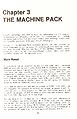
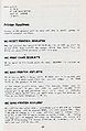
Broadly speaking, the Machine Pack is reponsible for the control of hardware peripherals, but it will be convenient to include the main initialisation processes under this heading, since they are largely concerned with peripheral setting-up.
Several of the Machine Pack routines depend on the action of other routines to set up data. To understand this data in full, you need to read 'The Ins and Outs of the AMSTRAD CPC464', which gives full details of the peripheral codes. Only the more essential codes will be defined here.
MAIN RESET
At switch—on, or in response to instruction code &C7, location 0000 is entered. At switch-on, lower ROM is enabled, but the ROM routines are later copied to the corresponding RAM locations in this area, so the enable state of the lower ROM is then unimportant. However, the first action of the reset routine is to output &89 to the Video Gate array on I/0 address 7FXX, and this enables lower ROM, disables upper ROM, and also sets up Mode 1. There being no further room in the RST Area the routine jumps to 0580 to continue reset action.
Interrupt is disabled, and &82 is output to F7XX. This sets the PPI (Parallel Peripheral Interface) to output on ports A and C, input on port B. Zero outputs to F4XX and F6XX clear ports A and C, while an output of &7F to EFXX initialises the printer port. Bit 7 is low, the other bits are high.
The CRT Controller is then set up. There are two alternative sets of values for this, one for 50 Hz frame scan and the other for 60 Hz. The set to be used is determined by reading port B, bit 4. If this bit is true, 50 Hz values are used, while the 60 Hz values are used if the bit is false, this being determined by the presence of Link 4 on the main printed circuit board.
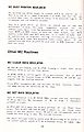
The tables are read backwards, which can be a little confusing at first, and the outputs alternate between BCXX, which selects the register to be set, and BDXX, which performs the actual setting.
Then MC START PROGRAM is entered at 060E with DE=065C and HL=0000. The contents of DE point to the display routine for the main title, which is called at an appropriate point. The zero value in HL means that ROM 0 will be entered at C006. This will normally invoke the BASIC interpreter, unless an external ROM responds to 0. C006 is the standard upper ROM entry point.
Before discussing MC START PROGRAM, it will be convenient to look at a program which calls it, having first loaded the necessary data:
MC BOOT PROGRAM: BD13,05DC
On entry to this function, HL must hold the address of a loading routine, which must be designed to return with carry set and the program start address in HL if the load is successful, or with carry clear if the load fails.
The stack is reset by SP=C000, this being the normal stack position, and sound RESET is called to silence the Sound Generator. Interrupt is disabled, and &FF is output to port F8FF, requiring that all external peripherals devices should be reset.
KL CHOKE OFF is called to clear the B100-B1BF area to zeroes, though the previous contents of (B1A9/B) are first saved. (B1A9/A) holds the last-used foreground ROM entry address, which is copied to DE, while (B1AB) holds the last-used foreground ROM number, which is copied to B. (Note that the number of the ROM in current use is held in (B1A8), which is not preserved here.) If (B1AB) holds &FF the routine returns with C, D and E all zeroed.
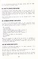
Back in the main BOOT routine, HL is restored to its value on entry and DE, BC and HL are pushed. KM RESET is called to initialise the Key Manager, TXT RESET is called to initialise the text screen, assisted by a call to SCR RESET, and U ROM ENABLE is called to bring the upper ROM into action.
HL is popped, and the loading program it defines is entered, using an odd little subroutine that consists solely of the JP (HL) instruction. BC and DE are popped.
If the loader returned with carry set, MC START PROGRAM is entered at 060B. Otherwise, DE and HL are exchanged, putting the address obtained by KL CHOKE OFF into HL, C=B, and MC START PROGRAM is entered at 060E with DE=06E8, the entry address of a routine that reports 'LOAD FAILED'. The previously-selected ROM is entered.
MC START PROGRAM: BD16,060B
If the normal entry to this function, at 060B, is used, DE is set to 0726 (pointing to a Return instruction), but it is also possible to enter at 060E, with DE pointing to a subroutine to be run during the latter part of the START PROGRAM routine. In either case, HL must hold the entry address to be used, and C must hold the number of the ROM to be employed, though the contents of C may be irrelevant if HL points to a RAM area.
Interrupt is disabled, and interrupt mode 1 is selected. The alternative BC, DE and HL registers are brought into action.
An output of 0 to DFXX selects upper ROM 0, and an output of &FF on I/0 address F8FF should reset external peripherals. Workspace in the B100-B8FF range is zeroed, and the Video Gate Array receives an output of &89 on address 7FXX. (Mode 1, enable lower, disable upper.) The normal BC, DE and HL registers are re-selected. XOR A zeroes A and clears carry, and EX AF ,AF' exchanges AF registers. This sets up the initial conditions required by the interrupt system.
The stack pointer is again set to C000, its normal base, and HL, BC and DE are pushed. A series of calls then performs the main initialisation;
- To 0044, copying the RAM routines from RAM, with KL CHOKE OFF following.
- JUMP RESTORE resets the jumpblock entries.
- KM INITIALISE resets the Key Manager.
- SOUND RESET initialises the Sound system.
- TXT INITIALISE initialises the Text VDU.
- GRA INITIALISE initialises the Graphics VDU.
- CAS INITIALISE initialises the Cassette Manager.
- MC RESET PRINTER standardises the printer system.
- SCR INITIALISE initialises the Screen Pack.
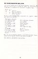
The details of these routines will be examined in the appropriate place, but it can be said that everything - or nearly everything - is brought to a standard state. This can be annoying to someone who likes to set up non-standard conditions, but it has the great advantage that every program starts on the same basis.
Interrupt is now enabled, and the routine defined in DE on entry is called. This may be the initial title display, or a 'load failed' report, as defined below. The main program then pops BG and HL and jumps to 0077, which is the actual entry routine. This key routine is not accessible via the Jumpblock, which might be useful, because the system concept requires a fulll reset before a program is entered.
If HL holds 0000, the default entry to C006 in ROM 0 is executed, but otherwise the ROM is defined in A and the entry address in HL.
| 0077 | If HL=0000, HL=C006, A=0 | Default Values. |
| (B1A8)=A | ROM number. | |
| (B1AB)=A | Part of qualifier. | |
| (B1A9/A)=HL | Qualifier address. | |
| HL=ABFF | Initial HIMEM. | |
| DE=0040 | Initial LOMEM. | |
| BC=B0FF | Top of usable memory. |
This completes the MG START PROGRAM routine, apart from the routines called near the end:
065C This calls 0712, which reads port B, picking up bits 1-3, which are determined by links. According to the links set, the display announces that the name of the machine is one of the following:
- Arnold
- Amstrad
- Orion
- Schneider
- Awa
- Solovox
- Saisho
- Triumph
- Isp
The actual output to the display is handled by 06EB, which is also called with HL=066D to output the rest of the title, and finally with HL=0693 to complete the display.
06E8 HL=@6F4, pointing to '***PROGRAM LOAD FAILED***'
Scanned pages
page 19
page 20
page 21
page 22
page 23
page 24
page 25
page 26


