Difference between revisions of "MegaROM"
(Created page with "right == Description == The MegaROM is a low-cost replacement for a standard ROMBoard, but rather than using an array of 16k EPROMs as tradi...") |
Devilmarkus (Talk | contribs) |
||
| (35 intermediate revisions by 6 users not shown) | |||
| Line 5: | Line 5: | ||
| − | The MegaROM is a low-cost replacement for a standard ROMBoard, but rather than using an array of | + | The MegaROM is a low-cost replacement for a standard ROMBoard, but rather than using an array of 16 kb EPROMs as traditional ROMBoards use, the MegaROM uses a single 8x128k (1Mbit) or 8x256k (2Mbit) EPROM (or Flash EPROM) divided into 16 kb blocks. This not only reduces the size of the device significantly, but due to the fact that 16 kb EPROMs are a dying breed, it is much easier and cheaper to find a single 8x256k EPROM than buy sixteen 16 kb EPROMs. |
| + | The complete hardware of the MegaROM was developed by [[User:Bryce|Bryce]] of [[FutureSoft]]. The original idea came from discussions with [[TFM]] of [[FutureSoft]]. The main goals being that it would offer up to 16 ROM positions, be very low cost and be a single-sided PCB design so that it could be easily built by most electronic hobbyists. | ||
| − | + | It is the predecessor of the Flash ROM based [[MegaFlash]]. | |
| + | If you have any further questions regarding this project contact [[User:Bryce|Bryce]] through the Wiki Forum. | ||
== Warning / Disclaimer == | == Warning / Disclaimer == | ||
| Line 23: | Line 25: | ||
| − | The main component on the PCB is the EPROM itself. This may be any pin compatible 8x128k (8 virtual ROMs) or 8x256k (16 virtual ROMs | + | The main component on the PCB is the EPROM itself. This may be any pin compatible 8x128k (8 virtual ROMs) or 8x256k (16 virtual ROMs), see the list of compatible tested EPROMs below. The EPROM should have a response time of 200ns or less. The five other ICs are standard TTL Logic devices and only need to be of the type 74LSxx (74HCTxx, 74Fxx etc will also work but are not necessary in this application). The unconnected pins on the EPROM in the schematic above, should be connected to the associated Address and Data bus pins of the 50way connector. I just left them out for clarity. |
== Parts List == | == Parts List == | ||
| − | As always, one of my priorities is to keep the price as low as possible, the cost of the entire board should come in at | + | As always, one of my priorities is to keep the price as low as possible, the cost of the entire board should come in at around 10€. |
| − | Here’s the Parts list (including | + | Here’s the Parts list (including an 8x256k UV EPROM) and their approximate prices (Centronics version): |
{|{{Prettytable|width: 700px; font-size: 2em;}} | {|{{Prettytable|width: 700px; font-size: 2em;}} | ||
|''Component''||''Quantity''||''Price''||''Total'' | |''Component''||''Quantity''||''Price''||''Total'' | ||
|- | |- | ||
| − | | | + | |27C-2001-100 EPROM||1||3.90€||3.90€ |
|- | |- | ||
|74LS374||1||0.25€||0.25€ | |74LS374||1||0.25€||0.25€ | ||
| Line 50: | Line 52: | ||
|1K 1/4W Resistor||1||0.05€||0.05€ | |1K 1/4W Resistor||1||0.05€||0.05€ | ||
|- | |- | ||
| − | |1N4148||1||0.02€||0.02€ | + | |1N4148 Diode||1||0.02€||0.02€ |
|- | |- | ||
|32 Pole IC Socket||1||0.50€||0.50€ | |32 Pole IC Socket||1||0.50€||0.50€ | ||
| Line 72: | Line 74: | ||
|} | |} | ||
| − | Note: In the picture above and also in the price list, I have chosen to use a header connector on the PCB. I did this because I intend using the MegaROM on both a UK CPC464 and a German CPC6128 and by using a header connector I can swap the connection cable to suit which CPC I'm connecting to. | + | Note: In the picture above and also in the price list, I have chosen to use a header connector on the PCB. I did this because I intend using the MegaROM on both a UK CPC464 and a German CPC6128 and by using a header connector I can swap the connection cable to suit which CPC I'm connecting to. You may choose a direct connection to the PCB if you don't need this feature, dropping the price another few cents. |
| + | |||
| + | [[Image:MegaROM_Cables.png|400px|centre]] | ||
| + | |||
| + | |||
| + | The Following EPROMs have been tested and are compatible with the MegaROM: | ||
| + | |||
| + | {|{{Prettytable|width: 700px; font-size: 2em;}} | ||
| + | |''Size''||''Type''||''Part No.s'' | ||
| + | |- | ||
| + | |8x 128k||UV||27C1001, 27C010 | ||
| + | |- | ||
| + | |8x 128k||Flash||28F010, 29C010 | ||
| + | |- | ||
| + | |8x 256k||UV||27C2001, 27C020 | ||
| + | |- | ||
| + | |8x 256k||Flash||28F020, 29C020 | ||
| + | |- | ||
| + | |} | ||
== Construction Tips == | == Construction Tips == | ||
| Line 93: | Line 113: | ||
| − | The finished PCB is 73mm x 73mm. The four holes in each corner can be used for mounting within a housing or as I have done here, adding legs to keep the PCB off the desk. If you use metal parts as I did, you will need to add plastic | + | The finished PCB is 73mm x 73mm. The four holes (M3) in each corner can be used for mounting within a housing or as I have done here, adding legs to keep the PCB off the desk. If you use metal parts as I did, you will need to add plastic insulators beneath the metal parts to avoid short circuits or damaging the tracks that are routed under the metal. |
| + | Closing an IDC connector on a 50way flat cable can be a difficult task and if not done properly, may cost you a connector or two. I recommend first putting the cable in position and pushing it slightly closed to keep the cable in place, then place the connector in a bench vice with rubber between the metal of the vice and the connector, then slowly closing the vice on the connector until it reaches it's home position. You may have to re-position the connector a few times until it's completely closed. Bad connections with these connectors are the cause of many peripherals not working, the pins in the centre cause the most issues, so turn the connector 90° in the vice for a final squeeze to make sure these pins are properly connected. Don't try closing an IDC connector with a hammer, pliers or other tool that only applies pressure to a tiny area of the connector, it will break! | ||
== Using The MegaROM == | == Using The MegaROM == | ||
| Line 100: | Line 121: | ||
Using your favourite EPROM Programmer, you can burn the ROM images to the locations shown below. You can either do this ROM for ROM or compile one single ROM file to burn in one go. You should set the EPROM programmer to only write to the area required, in case you want to add additional ROMs later, any unwritten area will be regarded as empty by the CPC. Below you can see the memory allocation for each virtual ROM within the EPROM. This file is also available below in PDF Format. | Using your favourite EPROM Programmer, you can burn the ROM images to the locations shown below. You can either do this ROM for ROM or compile one single ROM file to burn in one go. You should set the EPROM programmer to only write to the area required, in case you want to add additional ROMs later, any unwritten area will be regarded as empty by the CPC. Below you can see the memory allocation for each virtual ROM within the EPROM. This file is also available below in PDF Format. | ||
| + | |||
| + | A full list of available ROMs can be found [[ROM|here]]. | ||
| Line 117: | Line 140: | ||
| − | + | [[Image:MegaROM_Screenshot.png|400px|centre]] | |
| + | The MegaROM is compatible with all 464, 664, 6128, 464+ and 6128+ and can be used to host standard ROM images such as [[AMSDOS]], [[BCPL]], [[FutureOS]], [[MAXAM]], [[Protext]], [[QuickCMD]], [[Utopia]], [[VDOS]], [[XD-DOS]]. A full list of available ROMs can be found [[ROM|here]]. | ||
| + | |||
| + | CPC Specific Limitations: | ||
| + | |||
| + | * CPC464/664 - The 464 and 664 only scan and initialise ROMs 7 to 0 at start-up. ROMs 15 to 8 are only accessable if manually initialised. | ||
| + | * CPC6128 - Classic CPC6128 can not overwrite the internal ROM 7 with an external device, to make use of the external ROM 7 the CPC must be modified to allow the internal ROM 7 to be disabled (eg: By adding a switch to the internal ROMs Chip Enable pin) | ||
| + | |||
| + | |||
| + | The MegaROM fully decodes the Address and Data buses, so it should not clash with any other official expansions installed in parallel or plus cartridges. However, adding two or more ROMBoards to a CPC in Parallel will cause crashes in some circumstances. | ||
== Resources == | == Resources == | ||
| Line 133: | Line 165: | ||
| − | + | [[Category:DIY]] [[Category:Expansion ROM]] [[Category:FutureOS]] [[Category:Peripherals]] | |
| − | + | ||
| − | + | ||
| − | + | ||
| − | + | ||
| − | + | ||
| − | + | ||
| − | + | ||
| − | + | ||
| − | + | ||
| − | [[Category: | + | |
Latest revision as of 17:37, 5 March 2013
Contents
Description
The MegaROM is a low-cost replacement for a standard ROMBoard, but rather than using an array of 16 kb EPROMs as traditional ROMBoards use, the MegaROM uses a single 8x128k (1Mbit) or 8x256k (2Mbit) EPROM (or Flash EPROM) divided into 16 kb blocks. This not only reduces the size of the device significantly, but due to the fact that 16 kb EPROMs are a dying breed, it is much easier and cheaper to find a single 8x256k EPROM than buy sixteen 16 kb EPROMs.
The complete hardware of the MegaROM was developed by Bryce of FutureSoft. The original idea came from discussions with TFM of FutureSoft. The main goals being that it would offer up to 16 ROM positions, be very low cost and be a single-sided PCB design so that it could be easily built by most electronic hobbyists.
It is the predecessor of the Flash ROM based MegaFlash.
If you have any further questions regarding this project contact Bryce through the Wiki Forum.
Warning / Disclaimer
Although I have taken the utmost care preparing this documentation, I do not guarantee that it is error free and I accept no responsibility for damage to anyone’s CPC, other personal equipment or injury inflicted on you or others.
The Circuit
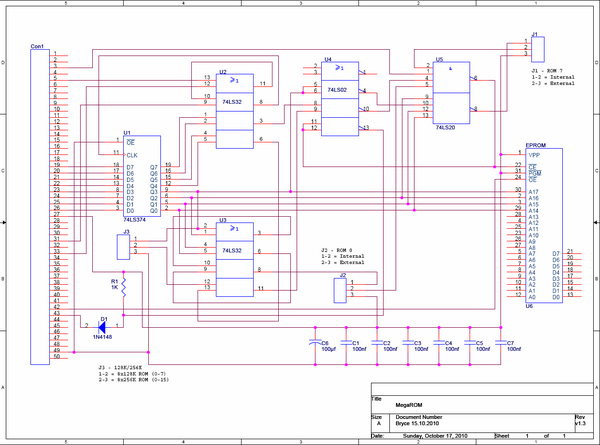
The main component on the PCB is the EPROM itself. This may be any pin compatible 8x128k (8 virtual ROMs) or 8x256k (16 virtual ROMs), see the list of compatible tested EPROMs below. The EPROM should have a response time of 200ns or less. The five other ICs are standard TTL Logic devices and only need to be of the type 74LSxx (74HCTxx, 74Fxx etc will also work but are not necessary in this application). The unconnected pins on the EPROM in the schematic above, should be connected to the associated Address and Data bus pins of the 50way connector. I just left them out for clarity.
Parts List
As always, one of my priorities is to keep the price as low as possible, the cost of the entire board should come in at around 10€. Here’s the Parts list (including an 8x256k UV EPROM) and their approximate prices (Centronics version):
| Component | Quantity | Price | Total |
| 27C-2001-100 EPROM | 1 | 3.90€ | 3.90€ |
| 74LS374 | 1 | 0.25€ | 0.25€ |
| 74LS32 | 2 | 0.32€ | 0.64€ |
| 74LS02 | 1 | 0.31€ | 0.31€ |
| 74LS20 | 1 | 0.33€ | 0.33€ |
| 100µf 16V Electrolytic Capacitor | 1 | 0.04€ | 0.04€ |
| 100nf Ceramic Capacitor | 6 | 0.03€ | 0.18€ |
| 1K 1/4W Resistor | 1 | 0.05€ | 0.05€ |
| 1N4148 Diode | 1 | 0.02€ | 0.02€ |
| 32 Pole IC Socket | 1 | 0.50€ | 0.50€ |
| 50 (2x25) way Header RM 2.54 | 1 | 0.19€ | 0.19€ |
| 3x 3 way header RM 2.54 (for jumpers) | 1 | 0.05€ | 0.05€ |
| Jumper Bridge | 3 | 0.05€ | 0.15€ |
| 50 way Centronics plug | 1 | 1.80€ | 1.80€ |
| 50 way flat cable | 1 | 0.20€ | 0.20€ |
| 50 flat cable connector | 1 | 0.25€ | 0.25€ |
| 160x100x1.5mm 35µ Single Sided photo-resist PCB | 1 | 1.70€ | 1.70€ |
| 10.56€ |
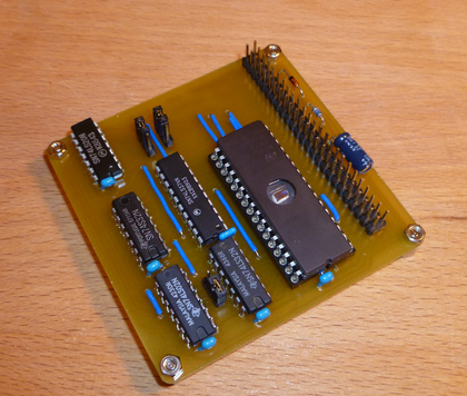
Note: In the picture above and also in the price list, I have chosen to use a header connector on the PCB. I did this because I intend using the MegaROM on both a UK CPC464 and a German CPC6128 and by using a header connector I can swap the connection cable to suit which CPC I'm connecting to. You may choose a direct connection to the PCB if you don't need this feature, dropping the price another few cents.
The Following EPROMs have been tested and are compatible with the MegaROM:
| Size | Type | Part No.s |
| 8x 128k | UV | 27C1001, 27C010 |
| 8x 128k | Flash | 28F010, 29C010 |
| 8x 256k | UV | 27C2001, 27C020 |
| 8x 256k | Flash | 28F020, 29C020 |
Construction Tips
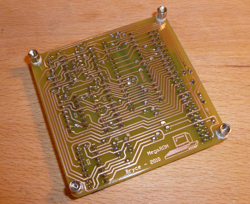
Due to the fact that I needed the PCB to be single-sided, I was forced to have quite a few bridges in the layout. These should be soldered on first, because I have placed as many as possible underneath the ICs to keep the design looking tidy. You should use insulated wire for the bridges to avoid short circuits, because they are very close to each other. In the documents below there is bridge layout plan with just the bridges highlighted to make things easier.
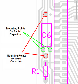
The other components may be added in the order you prefer. For C6 (100µf Electrolytic) there are mounting positions for both radial and axial type parts. You only need to drill the two holes you require, the other two should be left un-drilled.
The polarity of C6 and D1 is critical, the other capacitors and R1 may be soldered in either direction. The orientation for the ICs can be found in the part position layout file below.
The finished PCB is 73mm x 73mm. The four holes (M3) in each corner can be used for mounting within a housing or as I have done here, adding legs to keep the PCB off the desk. If you use metal parts as I did, you will need to add plastic insulators beneath the metal parts to avoid short circuits or damaging the tracks that are routed under the metal.
Closing an IDC connector on a 50way flat cable can be a difficult task and if not done properly, may cost you a connector or two. I recommend first putting the cable in position and pushing it slightly closed to keep the cable in place, then place the connector in a bench vice with rubber between the metal of the vice and the connector, then slowly closing the vice on the connector until it reaches it's home position. You may have to re-position the connector a few times until it's completely closed. Bad connections with these connectors are the cause of many peripherals not working, the pins in the centre cause the most issues, so turn the connector 90° in the vice for a final squeeze to make sure these pins are properly connected. Don't try closing an IDC connector with a hammer, pliers or other tool that only applies pressure to a tiny area of the connector, it will break!
Using The MegaROM
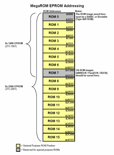
Using your favourite EPROM Programmer, you can burn the ROM images to the locations shown below. You can either do this ROM for ROM or compile one single ROM file to burn in one go. You should set the EPROM programmer to only write to the area required, in case you want to add additional ROMs later, any unwritten area will be regarded as empty by the CPC. Below you can see the memory allocation for each virtual ROM within the EPROM. This file is also available below in PDF Format.
A full list of available ROMs can be found here.
Jumper Settings
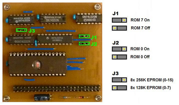
On the PCB there are three jumpers, which need to be set. Jumper 1 enables or disables ROM 7 on the MegaROM to allow use of the internal ROM on the 6128. Jumper 2 enables or disables ROM 0 on the MegaROM to choose between the CPCs internal Basic ROM or an alternative Boot ROM on the MegaROM. Jumper 3 is used to select which type of EPROM is installed. If a 8x128k EPROM is installed, the jumper must be set to the correct position otherwise the CPC will not boot. If a 8x256k EPROM is installed, the jumper can be set to 256k to enable all 16 ROMs or to 128k to disable the upper 8 ROMs (8-15).
Compatibility
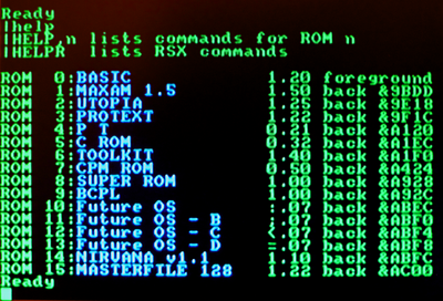
The MegaROM is compatible with all 464, 664, 6128, 464+ and 6128+ and can be used to host standard ROM images such as AMSDOS, BCPL, FutureOS, MAXAM, Protext, QuickCMD, Utopia, VDOS, XD-DOS. A full list of available ROMs can be found here.
CPC Specific Limitations:
- CPC464/664 - The 464 and 664 only scan and initialise ROMs 7 to 0 at start-up. ROMs 15 to 8 are only accessable if manually initialised.
- CPC6128 - Classic CPC6128 can not overwrite the internal ROM 7 with an external device, to make use of the external ROM 7 the CPC must be modified to allow the internal ROM 7 to be disabled (eg: By adding a switch to the internal ROMs Chip Enable pin)
The MegaROM fully decodes the Address and Data buses, so it should not clash with any other official expansions installed in parallel or plus cartridges. However, adding two or more ROMBoards to a CPC in Parallel will cause crashes in some circumstances.
Resources
File:MegaROM Layout.pdf - PCB Track Layout
File:MegaROM Bridges.pdf - PCB Bridge Position Layout
File:MegaROM Partpos.pdf - PCB Component Position Layout
File:MegaROM Memory Map.pdf - EPROM Memory Allocations Chart
