Difference between revisions of "Mirage Imager"
| Line 48: | Line 48: | ||
</gallery> | </gallery> | ||
| + | |||
| + | == Technical == | ||
| + | |||
| + | The following has been derived from the schematic and the ROM code. | ||
| + | |||
| + | The onboard 8KB Ram is read/written via port FCxx and FDxx with the following address decoding: | ||
| + | |||
| + | 1111110aaaaaaaaa | ||
| + | |||
| + | 'a' form part of the address for the RAM. The data read/written to the port is from the RAM. NOTE: The order of the data bits are scrambled/remapped. See the schematic. | ||
| + | |||
| + | The other bits are controlled by port FExx with this address decoding: | ||
| + | |||
| + | 1111111xxxxxxxxx | ||
| + | |||
| + | Here D3-D0 define the other parts of the RAM address. | ||
| + | |||
| + | NOTE: The addresses to the RAM are also scrambled/remapped. See the schematic. | ||
| + | |||
| + | The ROM is made visible by pressing the red button which causes an NMI. It maps the ROM into location 0000-1fff with a mirror at 2000-ffff. | ||
| + | The ROM replaces the internal CPC ROM and also disables the RAM where it is mapped. | ||
| + | |||
| + | The ROM state is also toggled by reading an opcode from an address >0x03000 and less than <0x03fff. The ROM itself uses 3FFB which contains a RET | ||
| + | instruction. It uses this to transition in and out of the ROM to read the font from the BASIC ROM. | ||
== Manual == | == Manual == | ||
Revision as of 09:26, 15 September 2018
An addon that enables you to freeze any program and store it to disc.
Made by Mirage Microcomputers Ltd.
The device was also available for the ZX Spectrum, this version was called the "Mirage Microdriver", and could save data either to tape or to Sinclair's "Microdrive"; an external high-speed tape drive.
The initial Spectrum version was released in 1985, although there was a later version released in 1986 (see Crash Issue 25, link below).
The CPC version was released in 1986.
The tool can backup RAM contents (including CPU registers pushed in RAM), but, unlike Multiface II, it cannot backup read-only I/O ports like CRTC (vram address/size) and Gate Array (screen colors) - the included software allows to manipulate that values manually (this would be only required with programs that use nonstandard CRTC value, or that use direct I/O to modify colors).
Now, thanks to Jose Leandro, the hardware specialist of the spectrum, with his famous page :
http://trastero.speccy.org/cosas/JL/JL.htm
We can know more about this hardware.
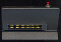
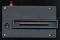
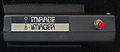
Pictures
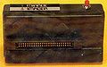
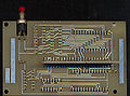
- Mirage Imager
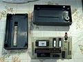
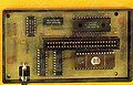
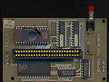
PCB
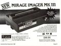
Advertisement of Mirage Imager MKIII


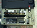
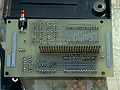
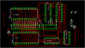
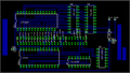
- Mirage Imager 300dpi scans by Robcfg


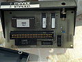
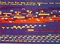
- Mirage Imager Layout, Thanks to Jose Leandro
PCB Front
PCB Back
Layout


Technical
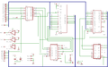
The following has been derived from the schematic and the ROM code.
The onboard 8KB Ram is read/written via port FCxx and FDxx with the following address decoding:
1111110aaaaaaaaa
'a' form part of the address for the RAM. The data read/written to the port is from the RAM. NOTE: The order of the data bits are scrambled/remapped. See the schematic.
The other bits are controlled by port FExx with this address decoding:
1111111xxxxxxxxx
Here D3-D0 define the other parts of the RAM address.
NOTE: The addresses to the RAM are also scrambled/remapped. See the schematic.
The ROM is made visible by pressing the red button which causes an NMI. It maps the ROM into location 0000-1fff with a mirror at 2000-ffff. The ROM replaces the internal CPC ROM and also disables the RAM where it is mapped.
The ROM state is also toggled by reading an opcode from an address >0x03000 and less than <0x03fff. The ROM itself uses 3FFB which contains a RET instruction. It uses this to transition in and out of the ROM to read the font from the BASIC ROM.
Manual
- Mirage Imager Manual (pdf) (v2, from 26 July 1986)
Downloads
- Mirage Image V3.2 (ROM).zip (ROM on RAW format, not valid for Emulators)
- Mirage Image V2 (ROM).zip (ROM on RAW format, not valid for Emulators)
Thanks to Jose Leandro :
- Mirage Imager ROM 3-2 (Good).zip (ROM for Emulators)
- Mirage Imager PALs.zip (PALs files)
- Mirage Imager PCBs.zip (PCBs files)
Weblinks
- Review (english) - Your Computer, 09/1986
- Review (german) - Happy Computer, 11/1986
- CPCrulez review (french) - Microstrad 8/Oct/1986