Difference between revisions of "Music Machine"
(→Pictures) |
(→Pictures) |
||
| Line 66: | Line 66: | ||
<gallery> caption="The Music Machine"> | <gallery> caption="The Music Machine"> | ||
Image:Music machine 1.jpg| | Image:Music machine 1.jpg| | ||
| − | Image:Music machine 2.jpg|missing | + | Image:Music machine 2.jpg|missing female connector (?) |
Image:Music machine back.jpg|Backside | Image:Music machine back.jpg|Backside | ||
Image:Music machine inside 1.jpg|PCB | Image:Music machine inside 1.jpg|PCB | ||
| Line 73: | Line 73: | ||
Image:Music machine microphone 1.jpg|The microphone | Image:Music machine microphone 1.jpg|The microphone | ||
Image:Music machine microphone 2.jpg|The microphone | Image:Music machine microphone 2.jpg|The microphone | ||
| + | Image:Rammusicmashine.jpg|With female connector | ||
</gallery> | </gallery> | ||
Revision as of 15:25, 18 June 2010

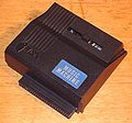
A digital sound sampling and playback device. The Music Machine was built by a British Company called Ram Electronics.
The Amstrad CPC version was almost identical to the the ZX Spectrum version, only difference was the address decoding logic.
The Music Machine came with a simple microphone. Recording quality could be improved by using a better(and more expensive) microphone. It came with its own sound sampling software and a sequencer.
No known emulator supports the Music Machine. There was a club advertised through the magazine Sinclare User which sent out a computer tape twice a year full of interesting software developed for the Ram Music Machine. This was contributed to by the members and included thing such as a 128k sampler, fsk syncing mods to the original software and many useful midi tools to name but a few.
The Music Machine was never used for producing sound effects in Demos.
Contents
Technical Specifications
Information from the manual:
The Music Machine incoporates two Ferranti devices for digital-to-analogue (DAC) and analogue-tod-digital (A to D) conversion. The part numbers are ZN429E8 and ZN449 respectively. The circuit also include a Motorola 6850 ACIA chip (Asynchronous Communications Interface Adapter) for handling the MIDI channel, two anti-alias filters (one for input and one for output), a discrete microphone amplifier and a headphone amplifier. The clock signal for the ACIA and the ZN449 is provided by a ceramic oscillator.
The incoming signal from the microphone amplifier is sampled to an 8-bit resolution at a rate of 19.444 thousand samples per second. This yields an analogue bandwidth of approximately 9.5KHz which is in fact the cutoff frequency of the filters.
The clock signal for the ACIA is unknown. As said above it is based one the same oscillator as used for the ZN449, however, the oscillator is probably whatever MHz (?) divided by whatever (?), and its unknown if the ACIA and ZN449 clocks are using the same divider (ie. the ZN449 samples at 19.444kHz, but the ACIA may, or may not, use another frequency).
All of the devices on The Music Machine data bus are accessible to the Amstrad within its I/O space. ACIA transactions must use 16-bit IO instructions; the converters are accesible via 8-bit IO instructions.
| I/O MapPortMeaning | ||
| &F8E8(Write only) | INTERUPT SEL | Writing 01 to this port disables internal Amstrad interrupts and replaces the IRQ signal from ACIA. Writing 00 restores normality. |
| &F8EC(Write only) | ACIA Control | See 6850 ACIA chip for details |
| &F8ED(Write only) | ACIA Data write | See 6850 ACIA chip for details |
| &F8EE(Read only) | ACIA Status | See 6850 ACIA chip for details |
| &F8EF(Read only) | ACIA Data read | See 6850 ACIA chip for details |
| &F8F0(Write only) | DAC WRITE | Data can written to the DAC via this port |
| &F8F4 (Read only) | ADC READ | The contents of the A-to-D can be read via this port. Note that the A-to-D must have been startet at least 20uS before this port can be read |
| &F8F8 | ADC START | Reading or writing to this port will start analogue to digital conversion |
Pictures
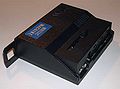

missing female connector (?)

Backside
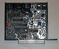
PCB
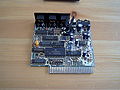
Inside 1

Inside 2
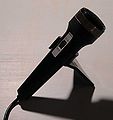
The microphone

The microphone
With female connector


Tape
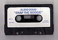
Music Machine Tape side B
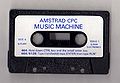
Music Machine Tape side A


Download
- Media:Music_Machine_Tape.zip - no such... ?
Manual
- Music Machine Manual (pdf)
Reviews
- Amstradbladet (1987, Issue 9, Page 22, and Page 23) (Danish)
- Amstrad Computer User (March 1987, Page 64, Page 65, and Page 66)
Weblinks
- Information about the Motorola 6850 ACIA
- Spanish site about the Music Machine
- Advert for the Music Machine
- Review
- Data transfer via MIDI[1]