Difference between revisions of "Arnold V Specs Revised"
(→Analogue paddle ports) |
(→6845's MA) |
||
| (21 intermediate revisions by 2 users not shown) | |||
| Line 87: | Line 87: | ||
Sixteen hardware sprites are to be provided by the ASIC. | Sixteen hardware sprites are to be provided by the ASIC. | ||
| − | Each consists of an array of 16x16 pixels of four bits per pixel. A sprite pixel is "transparent" when it has a value of zero, thus allowing 15 sprite colours. The sprite pixel data exists in memory mapped registers with the ASIC, from address 4000h. The lower four bits of each byte contain the data for a single pixel. The first 16 bytes contain the data for the upper scan line, starting at the top left hand corner of the sprite. 15 more similar scan lines of 16 pixels each follow, thus each 256 (0100h) byte block of register space contains one sprite. When the data for a sprite is read or written, that sprite is removed from the display for the duration of the access. Thus sprite data should only be accessed during retraced time | + | Each consists of an array of 16x16 pixels of four bits per pixel. A sprite pixel is "transparent" when it has a value of zero, thus allowing 15 sprite colours. The sprite pixel data exists in memory mapped registers with the ASIC, from address 4000h. The lower four bits of each byte contain the data for a single pixel. The first 16 bytes contain the data for the upper scan line, starting at the top left hand corner of the sprite. 15 more similar scan lines of 16 pixels each follow, thus each 256 (0100h) byte block of register space contains one sprite. When the pixel data for a sprite is read or written, that sprite is removed from the display for the duration of the access. Thus sprite pixel data should only be accessed during retraced time or while the raster is scanning somewhere else to avoid this. |
The position on screen of the upper left corner of each sprite, and the X and Y magnification, are defined by five registers for each sprite: | The position on screen of the upper left corner of each sprite, and the X and Y magnification, are defined by five registers for each sprite: | ||
| Line 115: | Line 115: | ||
All sprite characteristics are independent of the main screen mode, the unmagnified pixel size being as for screen mode 2 (640x200). Sprite colours are defined by 15 entries in the colour palette (see section 2.2 below). Thus sprites can be in different colours and resolutions from the rest of the screen. Sprites may overlay with each other or the border, and are prioritized so that the border has the highest priority, followed by sprites 0 to 15 in sequence, then the main screen data. Thus sprites always appear "in front of" the main screen and behind "the border". | All sprite characteristics are independent of the main screen mode, the unmagnified pixel size being as for screen mode 2 (640x200). Sprite colours are defined by 15 entries in the colour palette (see section 2.2 below). Thus sprites can be in different colours and resolutions from the rest of the screen. Sprites may overlay with each other or the border, and are prioritized so that the border has the highest priority, followed by sprites 0 to 15 in sequence, then the main screen data. Thus sprites always appear "in front of" the main screen and behind "the border". | ||
| − | When writing offsets +3,+4,+5 and +7 can set the sprite magnification. +4 to +7 are mirrors. | + | When writing offsets +3,+4,+5 and +7 you can set the sprite magnification. +4 to +7 are mirrors. |
| − | When reading +3 and +4 | + | When reading +3 and +4 you will read X position, +5 and +7 will read Y position. They are mirrors of X,Y values. |
| + | |||
| + | When the sprite pixel data is read or written, only the sprite whose pixels are being accessed is disabled (e.g. reading or writing in the range &4000-&40ff will only cause sprite 0 to be affected.). The pixels are not disrupted, the sprite will continue to be displayed after the read/write is done with no corruption to the image of the sprite. At the point the read/write is done, the sprite is disabled and what you will see behind is the pixels from a lower priority sprite or the background depending on what is behind. The read/write interrupts the display of the sprite at that moment. A write of 1us seems to only affect a width of 1 byte (i.e. 4 mode 1 pixels) rather than the full 1us time. Writing to the sprite X,Y or magnification doesn't cause the sprite to be disabled, but note writing a different X or Y coordinate will cause the sprite to be cut and appear at the new location when it's reached. | ||
| + | |||
| + | If you update a sprite which is covered by a lower priority sprite or the border then you will not see the effect. | ||
===Colour palette=== | ===Colour palette=== | ||
| Line 144: | Line 148: | ||
10-1F border colour</pre> | 10-1F border colour</pre> | ||
| + | NOTE: If you use a 16-bit write to write to the palette (e.g. LD HL,&0FFF: LD (&6400),HL then you will see the colour change as a result of first the low byte, then the high byte so that if you are writing black and then white, you will see another colour at the point of changing the colours. If you don't want to see this, then you can use the CPC OUT method but be restricted to the 27 CPC colours). | ||
===Split Screen facility=== | ===Split Screen facility=== | ||
| Line 157: | Line 162: | ||
The full address that is displayed is defined by the soft scroll register, 6845's internal scan line counter and the programmed address. | The full address that is displayed is defined by the soft scroll register, 6845's internal scan line counter and the programmed address. | ||
| − | + | When VCC=R4 and RCC=R9 the programmed address is stored when 6845's Horizontal counter matches R0 on the line programmed, at other times the programmed address is stored when 6845's Horizontal counter matches Horizontal Displayed (R1) on the line programmed. | |
| − | + | The value is never used when VCC=0 and RCC=0, R12/R13 are always used here so you can't trigger the split to happen on the scanline before a new frame and change the MA of the first scanline of a frame. If you do the value is used at the next available line. (e.g. VCC=0, RCC=1). | |
| + | |||
| + | At all other times the programmed split value is used to set MA on the next scanline. | ||
| + | |||
| + | Note that because the address is loaded into MA it effects the rest of the screen until the next time it is re-programmed or the display restarts. | ||
Note that care should be taken with programming this facility such that the screen split does not alter the function of address bits A1-A8 and the dynamic memory refresh is not upset. This can be accomplished by setting the start of the second screen to lie on 16k boundary. The reason is that the dynamic memory refresh is derived from the memory address that the 6845 describes. | Note that care should be taken with programming this facility such that the screen split does not alter the function of address bits A1-A8 and the dynamic memory refresh is not upset. This can be accomplished by setting the start of the second screen to lie on 16k boundary. The reason is that the dynamic memory refresh is derived from the memory address that the 6845 describes. | ||
| Line 211: | Line 220: | ||
Setting the SSCR to zero, as at reset, (i.e. no offsets, no border), will of course effectively disable soft scroll. | Setting the SSCR to zero, as at reset, (i.e. no offsets, no border), will of course effectively disable soft scroll. | ||
| − | |||
| − | |||
| − | |||
| − | |||
| − | |||
| − | |||
| − | |||
| − | |||
| − | |||
===Automatic feeding of sound generator=== | ===Automatic feeding of sound generator=== | ||
| Line 273: | Line 273: | ||
The SAR must be loaded by the CPU with a physical RAM address between 0000h and FFFEh. This means that the most significant two bits select which pages 0 to 3 of the DRAM is used, and the remaining bits are the address relative to the page start. The DMA process is not affected by the RAM or ROM mapping registers, and will always fetch data from RAM and not ROM. Note that the least significant bit of the address is ignored, and the instructions are always fetched from word boundaries. | The SAR must be loaded by the CPU with a physical RAM address between 0000h and FFFEh. This means that the most significant two bits select which pages 0 to 3 of the DRAM is used, and the remaining bits are the address relative to the page start. The DMA process is not affected by the RAM or ROM mapping registers, and will always fetch data from RAM and not ROM. Note that the least significant bit of the address is ignored, and the instructions are always fetched from word boundaries. | ||
| − | The pause prescaler counts N+1 scan lines (where N is the value written by the CPU), giving a minimum tick of 64us, and a maximum of 16.384ms. When set nonzero by a pause instruction, the pause counter for a particular channel is decremented every tick until it reaches zero. Therefore, if the PPR is set to a value N and a PAUSE M instruction is executed, the total delay time between the instruction before the PAUSE and that following the PAUSE will be M * (N+1) * 64us. Pauses of between 64us and 67s may thus be generated. If a DMA channel is executing a pause when the SAR is changed, the pause counter will continue to decrement. If the DMA channel is disabled, the pause will stop decrementing for the period in which it is disabled, but it will not reset and when the DMA is again enabled and the command at the current SAR address will not be executed until the pause is complete. Changing the prescale value mid-pause will vary the length of the pause (eg. If the prescale is set to 0 and a PAUSE 10 is executed and has already decremented 5 times, changing the prescale to 1 will cause the pause to have a duration of 15 scan lines). | + | The pause prescaler counts N+1 scan lines (where N is the value written by the CPU), giving a minimum tick of 64us, and a maximum of 16.384ms. When set nonzero by a pause instruction, the pause counter for a particular channel is decremented every tick until it reaches zero. Therefore, if the PPR is set to a value N and a PAUSE M instruction is executed, the total delay time between the instruction before the PAUSE and that following the PAUSE will be M * (N+1) * 64us. Pauses of between 64us and 67s may thus be generated. If a DMA channel is executing a pause when the SAR is changed, the pause counter will continue to decrement. If the DMA channel is disabled, the pause will stop decrementing for the period in which it is disabled, but it will not reset and when the DMA is again enabled and the command at the current SAR address will not be executed until the pause is complete. The loop counter is presumably not reset either when the channel is disabled (unconfirmed). Changing the prescale value mid-pause will vary the length of the pause (eg. If the prescale is set to 0 and a PAUSE 10 is executed and has already decremented 5 times, changing the prescale to 1 will cause the pause to have a duration of 15 scan lines). |
The ASIC arbitrates accesses to the parallel interface device between the "DMA" channels and the CPU, allowing only one to access it at a time. CPU accesses to the 8255 could be held off by means of wait states for up to 8 microseconds if the "DMA" channel is currently executing a LOAD instruction. After a LOAD is executed, the ASIC must put the PSG address register back as it was before. To achieve this the 8255 parallel peripheral interface and the 74LS145 decoder have been integrated into the ASIC. | The ASIC arbitrates accesses to the parallel interface device between the "DMA" channels and the CPU, allowing only one to access it at a time. CPU accesses to the 8255 could be held off by means of wait states for up to 8 microseconds if the "DMA" channel is currently executing a LOAD instruction. After a LOAD is executed, the ASIC must put the PSG address register back as it was before. To achieve this the 8255 parallel peripheral interface and the 74LS145 decoder have been integrated into the ASIC. | ||
| Line 281: | Line 281: | ||
* AY selected register | * AY selected register | ||
* AY read/write operation | * AY read/write operation | ||
| − | |||
| − | |||
| − | |||
The exact timing is based on 1us cycles as follows. After the leading edge from HSYNC from the 6845 there is one dead cycle followed by an instruction fetch cycle for each channel which is active (i.e. enabled and not paused). The execute cycles then follow for each active channel. All instructions execute in one cycle, except that LOAD requires at least 8 cycles. An extra cycle is added to a LOAD if the CPU is accessing the 8255, or two extra cycles if the CPU access was itself a PSG register write. | The exact timing is based on 1us cycles as follows. After the leading edge from HSYNC from the 6845 there is one dead cycle followed by an instruction fetch cycle for each channel which is active (i.e. enabled and not paused). The execute cycles then follow for each active channel. All instructions execute in one cycle, except that LOAD requires at least 8 cycles. An extra cycle is added to a LOAD if the CPU is accessing the 8255, or two extra cycles if the CPU access was itself a PSG register write. | ||
| Line 315: | Line 312: | ||
</pre> | </pre> | ||
| − | The value written to bit D0 of the IVR controls whether DMA channel interrupts are automatically cleared. The contents of register 6805h are undefined at reset except that bit D0 will be set to 1. Software should always set up the IVR before placing the CPU in vectored interrupt | + | The value written to bit D0 of the IVR controls whether DMA channel interrupts are automatically cleared. The contents of register 6805h are undefined at reset except that bit D0 will be set to 1. Software should therefore always set up the IVR before placing the CPU in vectored interrupt so that the top bit 5 bits are defined. |
The interrupts are prioritized in a fixed sequence. The raster interrupt has the highest priority, followed by DMA channels 2 down to 0 respectively. For compatibility with earlier models, the raster interrupt is reset either by a CPU interrupt acknowledge cycle, or by writing a 1 to bit D4 of the mode and ROM enable register. The sound channel interrupts are cleared by writing a 1 to the relevant bit in the DCSR. To simplify vectored interrupt systems, they may also be cleared automatically by a CPU interrupt acknowledge cycle. This feature is enabled by writing a 0 to bit D0 of IVR. | The interrupts are prioritized in a fixed sequence. The raster interrupt has the highest priority, followed by DMA channels 2 down to 0 respectively. For compatibility with earlier models, the raster interrupt is reset either by a CPU interrupt acknowledge cycle, or by writing a 1 to bit D4 of the mode and ROM enable register. The sound channel interrupts are cleared by writing a 1 to the relevant bit in the DCSR. To simplify vectored interrupt systems, they may also be cleared automatically by a CPU interrupt acknowledge cycle. This feature is enabled by writing a 0 to bit D0 of IVR. | ||
| + | |||
Bit D7 is set if the last interrupt acknowledge was for a raster interrupt. Bits D6-D4 of the DCSR are set if interrupts from sound channels 0-2 respectively are active. These bits can be ignored by software which uses vectored interrupts where the DMA interrupts are automatically cleared, or by software which does not use the DMA channel interrupt facility. If DMA channel interrupts are used and not automatically cleared, they must be acknowledged by writing a “1” to the relevant DCSR bit. If bit D0 of the IVR is set to 0 bits D4-D6 of the DCSR will be cleared before the CPU gets a chance to read them. | Bit D7 is set if the last interrupt acknowledge was for a raster interrupt. Bits D6-D4 of the DCSR are set if interrupts from sound channels 0-2 respectively are active. These bits can be ignored by software which uses vectored interrupts where the DMA interrupts are automatically cleared, or by software which does not use the DMA channel interrupt facility. If DMA channel interrupts are used and not automatically cleared, they must be acknowledged by writing a “1” to the relevant DCSR bit. If bit D0 of the IVR is set to 0 bits D4-D6 of the DCSR will be cleared before the CPU gets a chance to read them. | ||
| + | |||
| + | If IVR bit 0 is set to 1, a DMA channel is interrupting and is not acknowledged then it will continue to interrupt until it is acknowledged. | ||
| + | |||
| − | Thus interrupt service software in an environment where DMA interrupts are used must inspect these bits, giving highest priority to the raster interrupt, because this interrupt is always cleared automatically. | + | Thus interrupt service software in an environment where DMA interrupts are used must inspect these bits, giving highest priority to the raster interrupt, because this interrupt is always cleared automatically. Failure to observe this requirement may result in raster interrupts being missed. |
| − | Failure to observe this requirement may result in raster interrupts being missed. | + | |
| − | Software which uses interrupts from expansion cards must always use Z80 non-vectored interrupt mode 1, because the expansion bus does not support vectored interrupts. | + | Software which uses interrupts from expansion cards must always use Z80 non-vectored interrupt mode 1, because the expansion bus does not support vectored interrupts. (The ASIC doesn't recognise the RETI command sequence and the expansion bus doesn't support IEO or IEI which is used to control IM2 interrupt priority.) |
To summarize, vectored software should place a valid vector (D0 = 0) into the IVR. The hardware will supply a different vector for each interrupt source, and all interrupts are acknowledge automatically. | To summarize, vectored software should place a valid vector (D0 = 0) into the IVR. The hardware will supply a different vector for each interrupt source, and all interrupts are acknowledge automatically. | ||
Non vectored software must write a "1" to bit D0 of the IVR, or leave it in it's reset state. Interrupt service software must examine bit D7 of the DCSR first, followed by bits D4-D6 (in any sequence) to identify the interrupt source. DMA interrupts must be acknowledged by writing a "1" to the relevant DCSR bit. | Non vectored software must write a "1" to bit D0 of the IVR, or leave it in it's reset state. Interrupt service software must examine bit D7 of the DCSR first, followed by bits D4-D6 (in any sequence) to identify the interrupt source. DMA interrupts must be acknowledged by writing a "1" to the relevant DCSR bit. | ||
| + | |||
| + | Vectored interrupts are bugged. See [[Plus Vectored Interrupt Bug]] for more details. | ||
===Enhanced ROM cartridge support=== | ===Enhanced ROM cartridge support=== | ||
| Line 436: | Line 438: | ||
Because of timescale pressures, the data separator design in the ASIC has been deleted rather than improved . Thus all models with a disk drive use an external SED9420 data separator. | Because of timescale pressures, the data separator design in the ASIC has been deleted rather than improved . Thus all models with a disk drive use an external SED9420 data separator. | ||
| + | |||
| + | === 6845's MA === | ||
| + | |||
| + | NOTE: The 6845 has an internal "stored" MA. The current MA count is reloaded with this value at the start of each line. There are 3 times when this value is updated: | ||
| + | # When the split screen address is set, split screen line has been reached and Horizontal Counter equals Horizontal Displayed. | ||
| + | # When Raster Counter + Soft scroll matches R9 and Horizontal Counter equals Horizontal Displayed. | ||
| + | # When Vertical character count is reset to 0, it is then loaded from R12 and R13. | ||
| + | |||
| + | It is therefore possible to simulate split screen, by setting the soft scroll at the time correct time, then setting it back to 0 immediately after. | ||
| + | |||
| + | ===8255=== | ||
| + | |||
| + | * When switching port A of ASICs emulated 8255 to input, FF is present on the emulated 8255's port A outputs. | ||
| + | |||
| + | This will cause an invalid PSG register to be selected: | ||
| + | |||
| + | ld bc,&f400 | ||
| + | out (c),c | ||
| + | ld bc,&f6c0 | ||
| + | out (c),c | ||
| + | ld bc,&f792 | ||
| + | out (c),c | ||
| + | ;; At this point FF appears in emulated 8255 port A. This selects an invalid PSG register '&ff', when read &FF is returned. This is one source of keyboard reading bugs. | ||
| + | |||
| + | Therefore use this: | ||
| + | |||
| + | ld bc,&f400 | ||
| + | out (c),c | ||
| + | ld bc,&f6c0 | ||
| + | out (c),c | ||
| + | ld bc,&f600 ;;; << use inactive | ||
| + | out (c),c | ||
| + | ld bc,&f792 | ||
| + | out (c),c | ||
| + | |||
| + | * When switching input/output of port A, on a normal 8255, the outputs are all cleared to 0. This doesn't happen on the emulated 8255. This is another source of keyboard reading bugs. | ||
===Reading of write-only I/O registers=== | ===Reading of write-only I/O registers=== | ||
Latest revision as of 18:59, 13 May 2024
full technical details for the Amstrad Plus range
Copyright Amstrad ©1990 plcNote: this text is not the original document as published by Amstrad; instead, Executioner and Arnoldemu has corrected some (or all?) of the mistakes found therein and added additional clarification. For the original document, look here, for more original documents see: Original Arnold V Specs.
Contents
- 1 PRODUCT RANGE OVERVIEW
- 2 TECHNICAL SPECIFICATIONS
- 2.1 Hardware Sprites
- 2.2 Colour palette
- 2.3 Split Screen facility
- 2.4 Programmable raster interrupt
- 2.5 Soft scroll facility
- 2.6 Automatic feeding of sound generator
- 2.7 Interrupt service (Vectored interrupts)
- 2.8 Enhanced ROM cartridge support
- 2.9 Analogue paddle ports
- 2.10 PAL subcarrier locking
- 2.11 Locking of enhanced features
- 2.12 Eight bit printer support
- 2.13 Floppy disc data separator
- 2.14 6845's MA
- 2.15 8255
- 2.16 Reading of write-only I/O registers
- 2.17 Reading of unmapped ASIC register RAM
- 2.18 Digital joysticks
- 2.19 Power requirements
- 3 SOFTWARE SPECIFICATION
- 4 MECHANICAL SPECIFICATION
- 5 DISPLAY DEVICES
- 6 NATIONAL VARIANTS
- 7 PACKING LIST
- 8 APPENDIX 1
- 9 APPENDIX II
PRODUCT RANGE OVERVIEW
This project provides a more sophisticated and stylish replacement for the earlier CPC464 and CPC6128 computers. This has been achieved by:
- Redesigning the ASIC and main PCB to incorporate a number of new features
- Restyling the casework to provide a more modern appearance.
Common Features
The casework consists of a new two piece set of plastic mouldings. This contains a horizontally mounted, double-sided PCB assembly on which are mounted most of the electronics for the computer. A small, vertically mounted , daughter PCB provides the connector for a ROM cartridge. Any size ROM cartridge from 16k x 8 up to 512k x 8 can be installed. The firmware, fitted to the main PCB on earlier CPC computers, is supplied instead in a ROM cartridge.
All expansion and peripheral device connectors are mounted on the main PCB. In addition to the connectors used on the existing CPC range, there are:
- Separate connectors for two joysticks, replacing the old daisy-chain arrangement. However, the daisy chain system can still be used on the Joystick 1 connector if required.
- An additional 15-way female D-type connector will provide four analogue input channels and access to the four existing "fire" buttons. This is pin compatible with the games control port on the PC200 (PC-8) computer.
- All PCB edge connectors have been replaced by types that are easier to screen against spurious RF emission. The printer connector is a 25-way female D type, as used on the PC1640 etc, and the expansion connector is a 50-way Delta (Centronics style) type, as used for the earlier CPC range in Germany.
The 6128's TAPE socket has been replaced by a 6 pin RJ-11 type for the light gun.
The computer provides stereo sound via additional pins on the monitor connector, as well as from the stereo sound socket.
All existing CPC electrical features are provided, plus some new features. There is complete backward compatibility except that:
- The border colour is undefined at power-on reset
- The new 6128 version has no tape socket
The following new features become available once a software "lock" has been opened, thus preventing existing CPC software from accidentally invoking them:
- 16 Sprites, each consisting of 16x16 high resolution pixels, in fifteen colours separate from the main screen colours. Each sprite can be magnified in X or Y, moved around the screen , and turned on or off independent of the main screen. Sprite pixels can be transparent, and sprites have a fixed order of priority (i.e. "depth"), so that they can pass in front of each other, in front of the main screen, and behind the border.
- The colour palette has been extended to allow simultaneous display of up to 32 colours (16 main + 15 sprite + border) from a palette of 4096, rather than the previous 17 from 27.
- Additional screen controls have been added, to allow split screen operation and smooth scrolling to be used.
- An automated sound generation process allows generation of more complex sound effects with greatly reduced software overhead.
- Some other internal features to ease implementation of better games software, described in the technical specifications section.
The functions of display monitor and power supply are provided by either:
- A restyled range of monitors, consisting of a white tube monochrome monitor MM12 and an improved colour monitor CM14.
- An MP2-style modulator/power supply unit.
- A Peritel adaptor/power supply unit.
The old CPC6128 keyboard is used, except that the colour scheme has been changed and the connecting cable exits in a different location.
Amstrad 464 Plus
This variant has an integral cassette tape drive, and 64k bytes of dynamic RAM. It is supplied with a ROM cartridge containing the system firmware plus the BASIC language, disk firmware and a game, although it is not possible to select the disk firmware.
Amstrad 6128 Plus
This variant will have an integral 3" floppy disk drive (5V) plus a 36-way Delta (Centronics style) expansion socket allowing a second 3" drive to be added. The 6128 Plus is to be supplied with a ROM cartridge containing the system firmware plus the BASIC language, disk firmware and a game. 128k bytes of dynamic RAM are fitted to the main PCB.
Further Variants
Unlike the existing CPC range, the size of dynamic RAM and whether or not a disk drive is installed are separately configurable options. It is therefore possible to produce a "4128" (128k diskless) or "664" (64k with disk) variant. Also, it is possible to increase the number of analogue input channels to eight.
TECHNICAL SPECIFICATIONS
The technical specification is essentially similar to the earlier CPC 464/6128 range, with some enhancements. This specification should therefore be read in conjunction the "Amstrad CPC 6128 Software Interface Spec" Issue 2, 17th February 1985. New features have been added by changes to the ASIC and main PCB circuitry.
The overriding concern in the specification of this new product range has been the need for total backward compatibility with the existing CPC range. Many of the new features within the ASIC employ new registers, which can be mapped to replace the page of RAM from 4000 to 7FFFh in the CPU memory map, by setting a bit pattern in an I/O port. Before this port is allowed to "exist", a deliberately obscure I/O sequence is needed. This mechanism protects existing CPC range software from accidents such as killing its own RAM page.
The following new features are provided by change to the ASIC and the main PCB electronics:
Hardware Sprites
Sixteen hardware sprites are to be provided by the ASIC.
Each consists of an array of 16x16 pixels of four bits per pixel. A sprite pixel is "transparent" when it has a value of zero, thus allowing 15 sprite colours. The sprite pixel data exists in memory mapped registers with the ASIC, from address 4000h. The lower four bits of each byte contain the data for a single pixel. The first 16 bytes contain the data for the upper scan line, starting at the top left hand corner of the sprite. 15 more similar scan lines of 16 pixels each follow, thus each 256 (0100h) byte block of register space contains one sprite. When the pixel data for a sprite is read or written, that sprite is removed from the display for the duration of the access. Thus sprite pixel data should only be accessed during retraced time or while the raster is scanning somewhere else to avoid this.
The position on screen of the upper left corner of each sprite, and the X and Y magnification, are defined by five registers for each sprite:
	A2 A1 A0

	0 0 0	X position LSB

	0 0 1	X position MSB

	0 1 0	Y position (scan line) LSB

	0 1 1	Y position MSB

	1 0 0	bits 3,2 = X magnification, bits 1,0 = Y magnification
The position registers are read/write, and accept numbers in two's complement form. They should only be changed during retrace or when a sprite is off. Data written to these registers should be between +767 and -256 for X, and between +255 and -256 for Y, otherwise the sprites will appear in strange positions. With standard 6845 timing (64us scan lines, 200 visible lines), on screen positions at maximum sprite magnification are -64 to +639 in x and -63 to +199 in y. A sprite will not be displayed if either the vertical or the horizontal positions outside the onscreen range. The magnification registers are cleared to zero at reset, and are write only. They are coded as:
0 0	Sprite not displayed
0 1	Magnification x1
1 0	Magnification x2
1 1	Magnification x4
The sprite control registers exist on 8-byte boundaries from addresses 6000 to 607Fh for sprites 0 to 15 respectively.
All sprite characteristics are independent of the main screen mode, the unmagnified pixel size being as for screen mode 2 (640x200). Sprite colours are defined by 15 entries in the colour palette (see section 2.2 below). Thus sprites can be in different colours and resolutions from the rest of the screen. Sprites may overlay with each other or the border, and are prioritized so that the border has the highest priority, followed by sprites 0 to 15 in sequence, then the main screen data. Thus sprites always appear "in front of" the main screen and behind "the border".
When writing offsets +3,+4,+5 and +7 you can set the sprite magnification. +4 to +7 are mirrors. When reading +3 and +4 you will read X position, +5 and +7 will read Y position. They are mirrors of X,Y values.
When the sprite pixel data is read or written, only the sprite whose pixels are being accessed is disabled (e.g. reading or writing in the range &4000-&40ff will only cause sprite 0 to be affected.). The pixels are not disrupted, the sprite will continue to be displayed after the read/write is done with no corruption to the image of the sprite. At the point the read/write is done, the sprite is disabled and what you will see behind is the pixels from a lower priority sprite or the background depending on what is behind. The read/write interrupts the display of the sprite at that moment. A write of 1us seems to only affect a width of 1 byte (i.e. 4 mode 1 pixels) rather than the full 1us time. Writing to the sprite X,Y or magnification doesn't cause the sprite to be disabled, but note writing a different X or Y coordinate will cause the sprite to be cut and appear at the new location when it's reached.
If you update a sprite which is covered by a lower priority sprite or the border then you will not see the effect.
Colour palette
The earlier colour palette within the ASIC, which selects 17 of 27 possible colours, has been replaced by a new palette which selects 32 of 4096 colours. This can be accessed through two ports. The primary port provides full access via 32 registers of 12 bits, i.e. 4 bits each for red, green and blue.
For compatibility with earlier models a secondary port provides access to the first 17 registers only (i.e. main screen colours and border), via the existing 5 bit interface. A block of logic maps the 5 bit colour written to the palette at the address selected by the "palette pointer register".
The primary palette port is between addresses 6400 and 643Fh, each pair of bytes representing one entry in the palette. The most significant byte contains the GREEN information in the lower nibble (D3-D0), and the other byte contains RED (D7-D4) and BLUE (D3-D0).
This ordering of colours has been selected to give the most consistent grey scale possible on a monochrome display (green is brighter than red, which is brighter than blue). However, because of the need to retain compatibility with the existing 27 level grey scale, the colours are summed with a 9:3:1 weighting rather than the 256:16:1 weighting which would be required to make the 12 bit word fully monotonic.
The primary palette registers appear in RAM low byte first, so that they can be loaded via a single 16-bit LD instruction, e.g. LD (6400h),0F00h would set the main colour 0 to bright green. The palette is dual ported so that there are no restrictions on when it can be accessed.
The primary port palette registers are:
	6400-641Fh	main screen colours 0 to 15

	6420-6421h	border colour

	6422-643Fh	sprite colours 1 to 15
The secondary port registers are:
	00-0F	main screen colours 0 to 15

	10-1F		border colour
NOTE: If you use a 16-bit write to write to the palette (e.g. LD HL,&0FFF: LD (&6400),HL then you will see the colour change as a result of first the low byte, then the high byte so that if you are writing black and then white, you will see another colour at the point of changing the colours. If you don't want to see this, then you can use the CPC OUT method but be restricted to the 27 CPC colours).
Split Screen facility
Three new memory mapped registers have been added within the ASIC, to provide a horizontally split screen facility. One at address 6801h defines the scan line after which the screen split occurs. A value of zero (as at power on reset) will turn this feature off.
The other register pair at 6802h and 6803h define the start address in memory to show for the split.
The screen can be split multiple times in a single frame by reprogramming 6801h, 6802 and 6803h.
The address takes the same form as R12 and R13 of the 6845 (e.g. &3000 for &c000). Any CRTC address can be used (the split may therefore scroll). 6802h is the high byte of the address and 6803h is the low byte of the address.
The full address that is displayed is defined by the soft scroll register, 6845's internal scan line counter and the programmed address.
When VCC=R4 and RCC=R9 the programmed address is stored when 6845's Horizontal counter matches R0 on the line programmed, at other times the programmed address is stored when 6845's Horizontal counter matches Horizontal Displayed (R1) on the line programmed.
The value is never used when VCC=0 and RCC=0, R12/R13 are always used here so you can't trigger the split to happen on the scanline before a new frame and change the MA of the first scanline of a frame. If you do the value is used at the next available line. (e.g. VCC=0, RCC=1).
At all other times the programmed split value is used to set MA on the next scanline.
Note that because the address is loaded into MA it effects the rest of the screen until the next time it is re-programmed or the display restarts.
Note that care should be taken with programming this facility such that the screen split does not alter the function of address bits A1-A8 and the dynamic memory refresh is not upset. This can be accomplished by setting the start of the second screen to lie on 16k boundary. The reason is that the dynamic memory refresh is derived from the memory address that the 6845 describes.
The value in register pair 6802h/6803h is the first displayed line and not the start address of the 16k block.
The internal comparison used :
SPLT7 SPLT6 SPLT5 SPLT4 SPLT3 SPLT2 SPLT1 SPLT0 == VC4 VC3 VC2 VC1 VC0 RC2 RC1 RC0
SPLT is the programmed value. The index denotes the bit number. VC is the internal CRTC vertical line counter. RC is the internal CRTC raster counter.
Also, during vertical retrace, the value in register 6801h should not be set to 257 less the total number of scan lines on the screen. The split line is 8-bit only and has a range of 0-255 and will wrap around (255->0). A normal screen has 312 scanlines. This means that with some values, the counter will wrap and the split line will occur 2 times. With a normal screen of 312 scan lines, the value 312 - 257 = 55, or 37h should not be programmed, otherwise instead of seeing a split at line 55, you see a split at line 2. To avoid this (1) the vertical total adjust register is set to 1 while 6801h contains 37h (or some other value where the wrap will occur before the new frame starts), or (2) the raster interrupt (see 2.4 below) should be used such that 6801h contains 0 during vertical retrace so that it is disabled and doesn't wrap.
EDIT: A programmed value of 1 shows 2 lines before the split. The value is captured when HCC=R1 on line 1, and used on the next line. A programmed value of 0 turns off the split. Therefore the only way to split to happen on the 2nd line is to ensure the counter wraps by setting the value to 55 (normal screen) as mentioned above.
EDIT: Screen split can occur during the first char line of vertical adjust (i.e. R5>0 and RC<=8) but not at any other time. i.e. RC>8). If R5 is set to 31, you can split during the first 8 lines only.
Programmable raster interrupt
A new 8 bit memory mapped register (PRI) has been added within the ASIC at address 6800h, which is cleared at power up. If zero, the normal raster interrupt mechanism (CPC style interrupts) functions as before. The PRI can be reprogrammed as required to produce multiple interrupts per frame. The raster interrupt is triggered on the trailing edge of the HSYNC sent to the monitor and the combined logic of HSYNC active AND raster matched. If the HSYNC position and duration programmed in the CRTC causes the HSYNC to still be active on the first horizontal character of a new scan line, the interrupt may occur twice for the programmed scan line (once at the start of the line, then again when the HSYNC starts at the end of the same line). See section 2.7 below for general information on interrupts.
Note that the raster interrupt doesn't trigger during Vertical Adjust time (defined by 6845's R5 register) and because of the way it is calculated, if you set 6845's R9 to less than 7, with some PRI values it will not trigger.
The position of the raster interrupt is based on the horizontal sync position (6845's R2) and horizontal sync width (6845's R3). Note that for a given value of R2 (here so that HSYNC is not active on the first horizontal character of a new scan line), values of 6 or greater for the horizontal sync position do not give a change in position, therefore it is triggered on the trailing edge of the HSYNC sent to the monitor and not the trailing edge of the HSYNC from the 6845. e.g. if Horizontal Sync width was set to 14, raster interrupt would trigger on cycle 6 not 14.
The internal comparison used:
0 PRI7 PRI6 PRI5 PRI4 PRI3 PRI2 PRI1 PRI0 == VC5 VC4 VC3 VC2 VC1 VC0 RC2 RC1 RC0
PRI is the programmed value. The index denotes the bit number. VC is the internal CRTC vertical line counter. RC is the internal CRTC raster counter.
NOTE: The CPC style 52-line counter interrupts will be active when PRI=0. This counter is always active. It operates the same as in the CPC. The position of this interrupt is determined by the horizontal sync position AND the horizontal sync width. Contrasting with the PRI based interrupts, this interrupt triggers on the trailing edge of the HSYNC from the 6845 and values greater than 6 DO cause a change in position.
Soft scroll facility
A memory mapped 8 bit soft scroll control register (SSCR) has been added within the ASIC at 6804h, to allow scrolling of the screen by pixels rather than just by characters at present. It is cleared at reset. This soft scrolling mechanism affects the whole of the main screen , regardless of the split screen facility, but it does not affect sprites.
The lower four bits (D3-D0) of the SSCR define a horizontal delay of between 0 and 15 bits i.e. high resolution (mode 2) pixels. This shifts the screen image to the right by the value programmed , "losing" pixels behind the right border and instead displaying random data on the left. It is left to the programmer to ensure that the delay value is always a multiple of the number of bits per pixel.
The next three bits (D6-D4) will be added to the least significant three bits of the scan line address the effect of this is to shift the display up by the number of scan lines programmed. The effect is immediate and can be turned "on" and "off" multiple times on the same line. Note however to get the expected result over the whole screen (so that the display is shifted up), the value must equal 6845's R9 when the 6845's Horizontal Counter matches 6845's R1. When it is active at this time, the current MA is stored and used on the next scanline. This allows the screen to be scrolled correctly.
The RA output of the 6845 is defined by the current raster count plus the soft scroll value (probably ANDed with &1f). This value doesn't effect the 6845's internal char line counter and raster counter, this explains why it behaves strangely when R9<7 is used, but works ok when R9>=8.
The most significant bit (D7), when set, causes the border to extend over the first two bytes (16 high resolution pixels) of each scan line, masking out the bad data caused by the horizontal soft scroll. Software which intends to use horizontal soft scroll should have this bit always set, so that the screen width does not keep changing.
Setting the SSCR to zero, as at reset, (i.e. no offsets, no border), will of course effectively disable soft scroll.
Automatic feeding of sound generator
An automatic process has been added to feed data to the sound generator from three instruction streams in main RAM without CPU intervention. Three separate channels each fetch one 16-bit instruction during horizontal retrace time. These instructions must be in usual Z-80 format, i.e. least significant bit first and must be aligned to word boundaries (i.e. address of first byte must be even). Once the three instructions have been captured , they are then executed sequentially. The maximum achievable update rate to the PSG is thus equal to the horizontal scan rate of 15.625 kHz per channel.
The available commands are :
- 0RDDh LOAD R,DD Load 8 bit data DD to PSG register R (0R015)
- 1NNNh PAUSE NNN Pause for N prescaled ticks (0 < N < 4095)
- 2NNNh REPEAT NNN Set loop counter to N for this stream (0 < N < 4095)and mark next instruction as loop start.
- 3xxxh (reserved) Do not use
- 4000h NOP No operation (64 us idle)
- 4001h LOOP If loop counter non zero, loop back to the first instruction after REPEAT instruction and decrement loop counter.
- 4010h INT Interrupt the CPU (see section 2.7 below)
- 4020h STOP Stop processing the sound list.
Note that :
- REPEAT Loops cannot be nested . Only one is allowed to be active per instruction stream at any time
- REPEAT 0 and PAUSE 0 instructions have no effect, i.e. they are equivalent to NOP.
- Control group (4xxxh) instructions can be logically ORed to produce more complex instructions, e.g. INT|STOP = h = Interrupt and stop.
- The STOP instruction will leave the source address register pointing to the next instruction, so that the instruction stream can be continued after CPU intervention.
- The argument field (N) of the REPEAT instruction is actually the number of times the loop is taken. The block of code between REPEAT and LOOP instructions is therefore executed N+1 times.
A DMA control and status register (DCSR) controls which channels are currently enabled, and also tells the CPU which channel is interrupting.
The channel enable bits in this register enable each "DMA" channel separately, and can be set by the CPU, and cleared by either the CPU, a STOP instruction, or power on reset. The interrupt bits are set when a channel is requesting an interrupt, and cleared when the CPU writes a "1" to the appropriate bit.
The control and status register bits are:
	D7	R	Raster interrupt (see 2.7 below)
	D6	R/W	Channel 0 interrupt
	D5	R/W	Channel 1 interrupt
	D4	R/W	Channel 2 interrupt
	D3		Unused (write 0)
	D2	R/W	Channel 2 enable
	D1	R/W	Channel 1 enable
	D0	R/W	Channel 0 enable
Each channel has a 16 bit source address register (SAR) and an 8 bit pause prescaler register (PPR). These are memory mapped, from address 6C00h, as follows:
	6C00h		Channel 0 address, LSB
	6C01h		Channel 0 address, MSB
	6C02h		Channel 0 prescaler
	6C03h		unused
	6C04-6C07h	Channel 1, as above
	6C08-6C0Bh	Channel 2, as above
	6C0F		Control and Status register
The SAR must be loaded by the CPU with a physical RAM address between 0000h and FFFEh. This means that the most significant two bits select which pages 0 to 3 of the DRAM is used, and the remaining bits are the address relative to the page start. The DMA process is not affected by the RAM or ROM mapping registers, and will always fetch data from RAM and not ROM. Note that the least significant bit of the address is ignored, and the instructions are always fetched from word boundaries.
The pause prescaler counts N+1 scan lines (where N is the value written by the CPU), giving a minimum tick of 64us, and a maximum of 16.384ms. When set nonzero by a pause instruction, the pause counter for a particular channel is decremented every tick until it reaches zero. Therefore, if the PPR is set to a value N and a PAUSE M instruction is executed, the total delay time between the instruction before the PAUSE and that following the PAUSE will be M * (N+1) * 64us. Pauses of between 64us and 67s may thus be generated. If a DMA channel is executing a pause when the SAR is changed, the pause counter will continue to decrement. If the DMA channel is disabled, the pause will stop decrementing for the period in which it is disabled, but it will not reset and when the DMA is again enabled and the command at the current SAR address will not be executed until the pause is complete. The loop counter is presumably not reset either when the channel is disabled (unconfirmed). Changing the prescale value mid-pause will vary the length of the pause (eg. If the prescale is set to 0 and a PAUSE 10 is executed and has already decremented 5 times, changing the prescale to 1 will cause the pause to have a duration of 15 scan lines).
The ASIC arbitrates accesses to the parallel interface device between the "DMA" channels and the CPU, allowing only one to access it at a time. CPU accesses to the 8255 could be held off by means of wait states for up to 8 microseconds if the "DMA" channel is currently executing a LOAD instruction. After a LOAD is executed, the ASIC must put the PSG address register back as it was before. To achieve this the 8255 parallel peripheral interface and the 74LS145 decoder have been integrated into the ASIC.
It is confirmed that the ASIC restores:
- 8255 (within ASIC) Port A direction.
- AY selected register
- AY read/write operation
The exact timing is based on 1us cycles as follows. After the leading edge from HSYNC from the 6845 there is one dead cycle followed by an instruction fetch cycle for each channel which is active (i.e. enabled and not paused). The execute cycles then follow for each active channel. All instructions execute in one cycle, except that LOAD requires at least 8 cycles. An extra cycle is added to a LOAD if the CPU is accessing the 8255, or two extra cycles if the CPU access was itself a PSG register write.
Example 1:
If DMA channel 0 and 2 are active:
<dead cycle>, <instruction fetch dma channel 0>, <instruction fetch dma channel 2>, <instruction execute dma channel 0>,<instruction execute dma channel 2>
Example 2:
If DMA channel 2 is only active:
<dead cycle>,<instruction fetch dma channel 2>,<instruction execute dma channel 2>
NOTE: DCSR is readable in the range 6c00-6c0f, but only appears to be writeable at 6c0f.
Interrupt service (Vectored interrupts)
The ASIC can produce interrupts from four sources: the raster interrupt and the three sound generator "DMA" channels. The ASIC will always supply a vector which can be used by the CPU in interrupt modes 0 and 2 or ignored in interrupt mode 1.
The top 5 bits of the vector will be supplied from bit D7-D3 of a memory mapped interrupt vector register (IVR) at address 6805h in the ASIC, and the next two bits will determine the source of the interrupt. Bit D0 of the vector supplied is always zero.
D2    D1    D0
 0     0     0    DMA channel 2 interrupt vector
 0     1     0    DMA channel 1 interrupt vector
 1     0     0    DMA channel 0 interrupt vector
 1     1     0    Raster interrupt vector
The value written to bit D0 of the IVR controls whether DMA channel interrupts are automatically cleared. The contents of register 6805h are undefined at reset except that bit D0 will be set to 1. Software should therefore always set up the IVR before placing the CPU in vectored interrupt so that the top bit 5 bits are defined.
The interrupts are prioritized in a fixed sequence. The raster interrupt has the highest priority, followed by DMA channels 2 down to 0 respectively. For compatibility with earlier models, the raster interrupt is reset either by a CPU interrupt acknowledge cycle, or by writing a 1 to bit D4 of the mode and ROM enable register. The sound channel interrupts are cleared by writing a 1 to the relevant bit in the DCSR. To simplify vectored interrupt systems, they may also be cleared automatically by a CPU interrupt acknowledge cycle. This feature is enabled by writing a 0 to bit D0 of IVR.
Bit D7 is set if the last interrupt acknowledge was for a raster interrupt. Bits D6-D4 of the DCSR are set if interrupts from sound channels 0-2 respectively are active. These bits can be ignored by software which uses vectored interrupts where the DMA interrupts are automatically cleared, or by software which does not use the DMA channel interrupt facility. If DMA channel interrupts are used and not automatically cleared, they must be acknowledged by writing a “1” to the relevant DCSR bit. If bit D0 of the IVR is set to 0 bits D4-D6 of the DCSR will be cleared before the CPU gets a chance to read them.
If IVR bit 0 is set to 1, a DMA channel is interrupting and is not acknowledged then it will continue to interrupt until it is acknowledged.
Thus interrupt service software in an environment where DMA interrupts are used must inspect these bits, giving highest priority to the raster interrupt, because this interrupt is always cleared automatically. Failure to observe this requirement may result in raster interrupts being missed.
Software which uses interrupts from expansion cards must always use Z80 non-vectored interrupt mode 1, because the expansion bus does not support vectored interrupts. (The ASIC doesn't recognise the RETI command sequence and the expansion bus doesn't support IEO or IEI which is used to control IM2 interrupt priority.)
To summarize, vectored software should place a valid vector (D0 = 0) into the IVR. The hardware will supply a different vector for each interrupt source, and all interrupts are acknowledge automatically.
Non vectored software must write a "1" to bit D0 of the IVR, or leave it in it's reset state. Interrupt service software must examine bit D7 of the DCSR first, followed by bits D4-D6 (in any sequence) to identify the interrupt source. DMA interrupts must be acknowledged by writing a "1" to the relevant DCSR bit.
Vectored interrupts are bugged. See Plus Vectored Interrupt Bug for more details.
Enhanced ROM cartridge support
Previously, 32k of firmware ROM existed in two 16k blocks. The low block was at addresses 0000 to 3FFFh, and the high block at C000 to FFFFh. Expansion ROMs were mapped into C000 to FFFFh by writing a code to I/O address DFxxh. The disk ROM was code 0 or 7, depending on the state of an expansion signal.
The new Arnold V range has no on board ROM, but instead has a cartridge slot which can support ROM cartridges of up to 4Mbits (512k bytes, or 32 pages in 16k bytes). This means that cartridge games cannot be copied, because there is no firmware available when the game is installed. However, any software house producing a game where the intermediate state of play or high score table can be saved must produce their own driver software.
The upper 5 ROM cartridge address lines are controlled by the ASIC via the existing ROM mapping port (at DFxxh), and hence define which of the 32 pages are mapped to the upper ROM block (C000 to FFFFh). The machine is supplied with a ROM cartridge containing the firmware and BASIC, and, where applicable, the disk ROM.
For values less than 128 written to the mapping port, the "BASIC" page of the cartridge is always selected at the high ROM block address, unless the value last written to the mapping port matches the current disk ROM code (i.e. either 0 or 7), in which case the "Disk" page is selected. For values greater than 127, the lower 5 bits set the cartridge ROM page number directly, so that the cartridge may be addressed at pages 128-159 (80h-9Fh).
The earlier expansion ROM mapping scheme using port DFxxh and ROMDIS on the expansion bus, still functions. The only change is that ROMDIS can now disable the disk ROM, and selecting the disk ROM does not cause ROMDIS to be activated. An expansion card ROM mapped at any page takes priority over the same page numbers in the cartridge.
In addition, new bits are defined in the mode and ROM enable (MRER) register at I/O address 7Fxxh, Previously D7 = 1 and D6 = 0 to select this register, and D5 should be 0. This has been modified such that, if this register is written with D5 = 1, the bottom five bits are redefined. This new register is known as the secondary ROM mapping register (RMR2). D4 and D3 control the address of the low bank, and also whether the memory mappped registers are enabled at 4000 to 7FFFh.
	D4  D3

	0    0		Low bank ROM = 0000 to 3FFFh, register page off
	0    1		Low bank ROM = 4000 to 7FFFh, register page off
	1    0		Low bank ROM = 8000 to BFFFh, register page off
	1    1		Low bank ROM = 0000 to 3FFFh, register page on
D2 to D0 determine which of the lower 8 pages of the cartridge ROM appear at the low bank address. The default is page 0.
The logical (as seen by the CPU) to physical (as appears to the upper five cartridge address lines), page translation scheme is thus :
Low bank:	Logical page (RMR2)	Physical page

			0-7		      0-7

High Bank:	Logical page (DFxxh)	Physical page

		0-127 (not disc page)	        1

		0 or 7 (disc page)	        3

		128-255		             0-31
This means that any of the first eight pages of cartridge ROM can be pages to either 0000, 4000, or 8000h, while any of the 32 cartridge pages can simultaneously appear at C000h.
The two ROM disable bits in the existing mode and ROM enable register disable the ROM as before, wherever it is mapped, as does the ROMDIS signal from the expansion bus. The "write through" mechanism, whereby writes to an area which is currently mapped as ROM actually write to the underlying RAM, still functions, wherever the ROM is mapped. However the write through mechanism cannot be used to access the register page. Write through also does not operate to the RAM from the register page.
At reset, page 0 is visible in the range &0000-&3fff. DFxx is reset to 0 at this time (logical page is set to 0). This means on GX4000 page 1 will be visible at &c000-&ffff. On the Plus, it depends on /EXP. If /EXP is low, page 1 will be visible at &c000-&ffff, otherwise page 3 will be visible and CPM will be auto booted.
On an unmodified GX4000, selecting logical page 7 using DFxx doesn't select physical page 3, instead it selects physical page 1. The appropiate hardware is not activated as it is on 464 and 6128.
Analogue paddle ports
The ASIC includes the logic for an octal A/D converter, in conjunction with an external R-2R network, comparator and analogue multiplexer. Eight analogue input channels are thus available on the PCB, of which only four have connectors. This allows support for four paddles or two joysticks, with capacity for twice this many without redesigning the ASIC. The A/D is 6 bits wide, to give sufficient resolution after calibrating joysticks. It appears to the software as a bank of eight, 6 bit, read-only registers from 6808h to 680Fh, known as ADC0-7. They are updated approximately 200 times per second. The A/D inputs have an input range of 0V (data = 00) to 2.5V (data = 3Fh), and an input impedance of 180k to Vcc.
On my 464, the default values with no joystick attached are &3f,&3f,&3f,&3f,&3f,&00,&3f,&00. With a Amstrad AJ-5 analogue joystick attached only channels 0 and 1 change. Channel 0 is the X movement and channel 1 is the Y movement.
The fire buttons on the joystick are mapped to digital joystick 0's fire 0 and fire 1.
PAL subcarrier locking
The main oscillator for the ASIC is 40MHz. A divide by 9 output at 4.444MHz is provided with a 5:4 mark/space ratio. It is possible to change the main crystal to 9 x 4.43619MHz = 39.90257 MHz, slowing the whole system by 0.25%. This may or may not upset the disk drives, but even if this is the case, a diskless unit could provide PAL subcarrier frequency locked to the master oscillator, thus improving the picture quality.
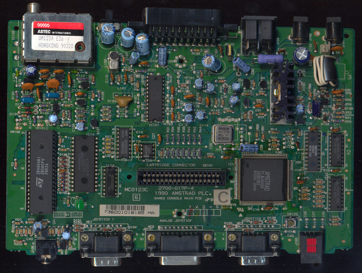
Note: The above applies only for the GX4000 with Composite video output (the GX4000 shares the same oscillator for the 4MHz CPU clock and 4.4MHz color clock) (not for 464+/6128+ with RGB output). As seen on this photo, the GX4000 does actually have a 39.90 MHz oscillator.
Locking of enhanced features
The ASIC contains a locking mechanism, whereby the enhanced features are not available until the software has performed an obscure sequence of I/O instructions to the ASIC. This prevents any existing software from having nasty accidents on the new hardware.
The lock is operated by writing a series of bytes to the 6845 address register at address BCxxh. The lock must first be synchronised by writing first a non zero byte value then a zero. The following sequence must then be written:
FF,77,B3,51,A8,D4,62,39,9C,46,2B,15,8A,CD,EE
The lock will then be picked.
When the lock is "locked", the secondary ROM mapping register does not exist (see Section 2.6). It is therefore impossible to select (or to deselect) the memory mapped register page.
The unlocking sequence has found to be:
<not zero> <zero>
&ff,&77,&b3,&51,&a8,&d4,&62,&39,&9c,&46,&2b,&15,&8a,&cd
<any value>
The locking sequence has found to be:
<not zero> <zero>
&ff,&77,&b3,&51,&a8,&d4,&62,&39,&9c,&46,&2b,&15,&8a
<any value - but not &cd>
Notes:
- asic is locked after hard reset (e.g. reset switch) or power on/off
- asic lock/unlock sequence enables/blocks the I/O port for making the ASIC registers visible in the z80 address space.
- asic lock remains in it's current state until the sequence completes
- asic lock doesn't disable the ram. So if you did unlock, enable ram, lock, then it will still be visible and you can read/write it.
However, now you can't disable it without unlocking the asic.
- all features, if programmed, remain active after lock, un-locking etc. They don't get cleared.
Note: As one may see, the nybbles in the sequence are based on two 4bit shift registers. For one reason or another, Amstrad has patented the verification mechanism (GB2243701A). The patent seems to focus on verifying (rather than on sending) the sequence, so its legal use is a bit unclear.
Eight bit printer support
The ASIC can provide support for eight bit printers. If a link on the PCB is made, the most significant printer port bit will be controlled by bit 3 in register 12 (decimal) of the 6845, i.e. bit 11 of the start address register. If the link is not made, the most significant printer port bit will always be low.
Note: The 8th bit is actually enabled by a 10kOhm resistor, not a wire-link, see LK Links for details.
Floppy disc data separator
Because of timescale pressures, the data separator design in the ASIC has been deleted rather than improved . Thus all models with a disk drive use an external SED9420 data separator.
6845's MA
NOTE: The 6845 has an internal "stored" MA. The current MA count is reloaded with this value at the start of each line. There are 3 times when this value is updated:
- When the split screen address is set, split screen line has been reached and Horizontal Counter equals Horizontal Displayed.
- When Raster Counter + Soft scroll matches R9 and Horizontal Counter equals Horizontal Displayed.
- When Vertical character count is reset to 0, it is then loaded from R12 and R13.
It is therefore possible to simulate split screen, by setting the soft scroll at the time correct time, then setting it back to 0 immediately after.
8255
- When switching port A of ASICs emulated 8255 to input, FF is present on the emulated 8255's port A outputs.
This will cause an invalid PSG register to be selected:
ld bc,&f400
out (c),c
ld bc,&f6c0
out (c),c
ld bc,&f792
out (c),c
;; At this point FF appears in emulated 8255 port A. This selects an invalid PSG register '&ff', when read &FF is returned. This is one source of keyboard reading bugs.
Therefore use this:
ld bc,&f400
out (c),c
ld bc,&f6c0
out (c),c
ld bc,&f600   ;;; << use inactive
out (c),c
ld bc,&f792
out (c),c
- When switching input/output of port A, on a normal 8255, the outputs are all cleared to 0. This doesn't happen on the emulated 8255. This is another source of keyboard reading bugs.
Reading of write-only I/O registers
The following has been tested:
When the following I/O ranges are read 7fxx, bcxx, bdxx, efxx and dfxx (these are write-only I/O registers), the last byte of the I/O read instruction is put onto the bus and read. e.g. if IN A,(C) is used to read from one of these ports, the last byte of that instruction is read back.
There is no hardware that is driving these registers so the data is what is last on the z80 data bus.
NOTE: That because 7fxx is mapped to gate-array and both read/write can access it it is possible to read the colour register and display a raster on the screen. In this case the raster will use colours based on the last byte of the instruction.
Reading of unmapped ASIC register RAM
When a read of an unmapped address is done from the ASIC register page (this is where there is no readable register here, or no register has been assigned), the last byte of the instruction used to do the read is return. e.g. if LD A,(&5000) is done, the last byte of this instruction is then read.
There is no hardware that is driving these registers so the data is what is last on the z80 data bus.
NOTE: Reading 6800-6806, which are mapped to write, also shows the same as unmapped addresses.
Digital joysticks
There is no dreaded "keyboard clash" between the digital joysticks, the fire buttons of the analogue joystick or the keyboard. This means that pressing a combination of buttons on the joystick and pressing keys on the keyboard don't result in a phantom key as they would on the CPC.
The keyboard itself suffers from keyboard clash however.
Power requirements
The Arnold V range is a 5V only design. Power requirements are:
Amstrad 464 Plus: MIN MAX UNIT
Main PCB 700 1300 mA
Cassette unit TBD TBD mA
Total consumption TBD TBD mA
Amstrad 6128 Plus: MIN MAX UNIT
Main PCB 700 1300 mA
Disk Drive unit 500 1100 mA
Total consumption 1200 2400 mA
SOFTWARE SPECIFICATION
The computers are shipped with a cartridge fitted in the cartridge slot. Disk based software is supplied with the 6128 Plus by Amstrad. There will be no welcome tape or disk.
6128
1M ROM cartridge (i.e. 128k x 8) Combined firmware, BASIC and Disk ROM, incorporating free game.
- Page 0: Firmware
- Page 1: BASIC
- Page 2: Game
- Page 3: Disk
- Pages 4-6: Game
- Page 7: BASIC
One 3" disk with CP/M Plus and utilities only.
464
1M ROM cartridge as for 6128
MECHANICAL SPECIFICATION
Both models in the new Arnold V range will share a common plastic cabinet. This will be a two-piece design, i.e. upper and lower cabinet halves. The name Amstrad will be moulded in to the top cabinet. The different variants will be handled by breakout sections or tool inserts as necessary. The 464 version will have the model name "464 Plus" moulded into the cassette door, and the "6128" version will have the model name "6128 Plus" moulded into the upper casework above the disk drive, in the areas of plastic which does not exist for the 464 version.
The monitors will have international symbols for brightness, contrast, volume and vertical hold. Apart from these items, there will be no moulded lettering, and moving cores must be kept to a minimum. The casework will provide both aesthetic and structural functions. Other moulded parts will be needed for the ROM cartridge, cartridge slot, cassette door, and power switch. These should be in the same material and the same colour as the main casework mouldings.
The power switch will be connected to a "bolt" which engages in the side of the ROM cartridge when the power is on, so that the cartridge cannot be inserted or withdrawn while power is applied to the machine. The main PCB, disk drive (6128) and cassette mechanism (464) will be mounted to the lower cabinet. Ideally, the keyboard should be similarly mounted on the lower cabinet, to improve serviceability, as should as many minor components as possible. A slimmer cassette mechanism must be used, to keep the height of the computer low. The cassette mechanism electronics will be mounted below the cassette deck, as with the old version.
DISPLAY DEVICES
With the CPC range, the display device, i.e. Monitor, Modulator/power supply, or peritel adaptor also supplies power to the computer. In view of the fact that RFI prevention will be important in Europe after 1992, all display devices should be to Class 1 construction, i.e. earthed, so that it is easier to prevent the computer radiating, and should themselves be designed to meet the RFI standard EN55022 (CISPR22). The monitors should operate off both 220V and 240V supplies without modification.
The relevant safety standard for this product is BS415 (IEC65).
MONITORS
The new Arnold V range will always be sold with a monitor.
The existing GTM65 and CTM640 monitors have been restyled in the same colour as the main cabinet. The monitor rear cabinet material must be to BS415 Clause 20.2
The MM12 monochrome incorporates a 12" paper white tube, similar to that used on the PCW9512. The input will be the same as the earlier GTM65 versions, i.e. impedance 470 ohms to 0V, analogue voltage input which is linear between 0.8V (Black) and 1.75V (Peak white).
The CM14 colour monitor needs to handle a sixteen level input on each of RGB. The new monitor must present an input impedance of 100 ohms to 0V, and accept an analogue input current of 0-10mA for each gun. The levels shall be defined such that 0mA is black and 10mA is full on. The response must be linear between these limits.
The monitors also incorporate stereo speakers, amplifiers, and a volume control. There is no 12V D.C. output.
Modulator/Power Supply units
The existing MP2 can be used with the new Arnold V range. However, it would be better to produce a new version following the RFI guidelines at the start of this section, and preferably including a sound modulator.
The input circuit of the Peritel adaptor will probably need to be redesigned to handle the new analogue video signals. It should also have the sound channels added.
NATIONAL VARIANTS
The existing national variants of the ROM (i.e. UK, France, Spain) will continue to be supported, but no others will be added. Steps should be taken to limit the amount of national variation to that which really is necessary. There should be no need to make any changes for approvals reasons, except to power supply input voltages and mains connectors.
There will be different versions of the keyboard, instruction book, and disk, as well as the ROM cartridge. It is thus possible to change between, variants without dismantling the computer.
PACKING LIST
The following items should be included in the computer carton:
- Polystyrene foam packing pieces
- The Amstrad 464 Plus or 6128 Plus unit, with ROM cartridge installed.
- A PD-1 Games paddle
- The instruction book
The following should be included in the monitor carton:
- Polystyrene foam packing pieces
- The MM12 or CM14 monitor
APPENDIX 1
New Register Map
The new register page, from 4000h to 7FFFh appears as follows:
	ADDR	SIZE	POR	TYPE	MNEM	USE

	4000h	100H	N	R/W		Sprite 0 image data
	4100h	100h	N	R/W		Sprite 1 image data
	|	|	|	|	|	|
	4F00h	100h	N	R/W		Sprite 15 image data

	5000h			  (unused)

	6000h	2	N	R/W	X0	Sprite 0 X position
	6002h	2	N	R/W	Y0	Sprite 0 Y position
	6004h	1	Y	W	M0	Sprite 0 magnification
	6005h	3		(unused)
	6008h	2	N	R/W	X1	Sprite 1 X position
	600Ah	2	N	R/W	Y1	Sprite 1 Y position
	600Ch	1	Y	W	M1	Sprite 1 magnification
	600Dh	3		(unused)
	|	|	|	|	|	|
	6078h	2	N	R/W	X15	Sprite 15 X position
	607Ah	2	N	R/W	Y15	Sprite 15 Y position
	607Ch	1	N	W	M15	Sprite 15 magnification
	607Dh	3		(unused)

	6080h			(unused)

	6400h	2	N	R/W		Colour palette, pen 0
	6402h	2	N	R/W		Colour palette, pen 1
	|	|	|	|	|	|
	641Eh	2	N	R/W		Colour palette, pen 15
	6420h	2	N	R/W		Colour palette, border
	6422h	2	N	R/W		Colour palette, sprite colour 1
	6424h	2	N	R/W		Colour palette, sprite colour 2
	|	|	|	|	|	|
	643Eh	2	N	R/W		Colour palette, sprite colour 15

	6440h			(unused)

	6800h	1	Y	W	PRI	Programmable raster interrupt scan line
	6801h	1	Y	W	SPLT	Screen split scan line
	6802h	2	N	W	SSA	Screen split secondary start address
	6804h	1	Y	W	SSCR	Soft scroll control register
	6805h	1	N	W	IVR	Interrupt Vector (Bit 0 set to 1 on reset)

	6806h       		(unused)

	6808h	1		R	ADC0	Analogue input channel 0
	6809h	1		R	ADC1	Analogue input channel 1
	680Ah	1		R	ADC2	Analogue input channel 2
	680Bh	1		R	ADC3	Analogue input channel 3
	680Ch	1		R	ADC4	Analogue input channel 4
	680Dh	1		R	ADC5	Analogue input channel 5
	680Eh	1		R	ADC6	Analogue input channel 6
	680Fh	1		R	ADC7	Analogue input channel 7

	6810h				(unused)

	6C00h	2	N	W	SAR0	"DMA" channel 0 address pointer
	6C02h	1	N	W	PPR0	"DMA" channel 0 pause prescaler
	6C03h	1			(unused)
	6C04h	2	N	W	SAR1	"DMA" channel 1 address pointer
	6C06h	1	N	W	PPR1	"DMA" channel 1 pause prescaler
	6C07h	1			(unused)
	6C08h	2	N	W	SAR2	"DMA" channel 2 address pointer
	6C0Ah	1	N	W	PPR2	"DMA" channel 2 pause prescaler
	6C0Bh	4			(unused)
	6C0Fh	1	Y	R/W	DCSR	"DMA" control/status register
Registers in I/O space are generally identical to earlier CPC464/6128 versions, except as follows:
	ADDR	DATA		POR	TYPE	MNEM	USE

	7Fxxh	00xxxxxx	N	W		Palette pointer register
	7Fxxh	01xxxxxx	N	W		Palette memory
	7Fxxh	100xxxxx	Y	W	MRER	Mode and ROM enable register
	7Fxxh	101xxxxx	Y	W	RMR2	Secondary ROM mapping register
	7Fxxh	11xxxxxx	Y	W		Memory mapping register (RAM)
	DFxxh	xxxxxxxx	Y	W		Expansion/Cartridge ROM select
Note that RMR2 can only be accessed when the new feature lock (Section 2.11 above) has been "opened". Otherwise, MRER exists in its place.
POR column indicates whether a register has power on reset. A "N" indicates that the contents of a register are undefined at power on.
At reset time, emulated PPI port A is set to input, port B is always input, port C is always output.
APPENDIX II
Connector pinouts
From front of left hand side rearwards, then along the rear panel towards the right, the connectors are:
SOUND: 3.5mm stereo jack
1 (Shield)      GND
2 (Tip)         L Sound
3 (Ring)        R Sound
JOYSTICK 1: 9 way male D. Joystick 2 can be daisy chained
 1	Up	6	Fire 2
 2	Down	7	Fire 1
 3	Left	8	Common
 4 	Right	9	Common (joystick 2)
 5	N.C.
JOYSTICK 2: 9 way male D.
 1	Up	6	Fire 2
 2	Down	7	Fire 1
 3	Left	8	Common
 4 	Right	9	N.C.
 5	N.C.
ANALOGUE: 15 way female D
 1	GND (Pot common)	9	GND (Pot common)
 2	Fire 1			10	Fire 1
 3	X1			11	X2
 4	COM1 (switches)	        12	COM2 (switches)
 5	+5V			13	Y2
 6	Y1			14	Fire 2
 7	Fire 2			15	GND (Pot common)
 8	GND (Pot common)
AUX: 6 pin RJ-11 type
  1	+5V
  2	Common
  3	LPEN
  4	Fire 2
  5	Fire 1
  6	GND
PRINTER: 25 way female D
1  *Strobe         14
2  D0              15
3  D1              16 +5V
4  D2              17 GND
5  D3              18 GND
6  D4              19 GND
7  D5              20 GND
8  D6              21 GND
9  D7              22 GND
10 ????            23 GND
11 BUSY            24 GND
12                 25 GND
13
EXPANSION: 50 way Delta range.
1	Sound		2	GND
3	A15		4	A14
5	A13		6	A12
7	A11		8	A10
9	A9		10	A8
11	A7		12	A6
13	A5		14	A4
15	A3		16	A2
17	A1		18	A0
19	D7		20	D6
21	D5		22	D4
23	D3		24	D2
25	D1		26	D0
27	VCC		28	*MREQ
29	*M1		30	*RFSH
31	*IORQ		32	*RD
33	*WR		34	*HALT
35	*INT		36	*NMI
37	*BUSRQ	        38	*BUSAK
39	READY	        40	*BRST
41	*RSET	        42	*ROMEN
43	ROMDIS	        44	*RAMRD
45	RAMDIS	        46	CURSOR
47	LPEN		48	*EXP
49	GND		50	CLK4
MONITOR: 8 way DIN type A (45326)
1	*Sync
2	Green
3	Lum
4	Red
5	Blue
6	L Sound
7	R Sound
8	GND
5 V DC: 6mm power
Centre +5V
X/Y Connector(? Probably keyboard matrix)
1	N.C.		1	Y1
2	X1		2	Y2
3	X2		3	Y3
4	X3		4	Y4
5	X4		5	Y5
6	X5		6	Y6
7	X6		7	Y7
8	X7		8	Y8
9	X8		9	Y9
10	N.C.		10	Y10
POWER SWITCH: 2 pin 0.1" pitch header
1	Input from PSU
2	+5V to Computer
POWER ON LED: 2 pin 0.1" pitch header
1	LED Anode
2	GND
ROM CARTRIDGE: 2 pcs 2 x 9 way 2.5mm pitch sockets.
  1a	A10	2a	A2	1b	+5V	2b	+5V
  3a	*CE	4a	A1	3b	CLK	4b	CA18
  5a	D7	6a	A0	5b	CA16	6b	CA17
  7a	D6	8a	D0	7b	CA15	8b	CA14
  9a	D5	10a	D1	9b	A12	10b	A13
  11a	D4	12a	D2	11b	A7	12b	A8
  13a	D3	14a	SIN	13b	A9	14b	A9
  15a	CCLR	16a	GND	15b	A5	16b	A11
  17a	GND	18a	GND	17b	A4	18b	A3