Difference between revisions of "Z80 STI RS232 interface"
(→The meaning and the Addresses of the registers) |
|||
| (17 intermediate revisions by 3 users not shown) | |||
| Line 1: | Line 1: | ||
== Intro == | == Intro == | ||
| − | This interface was originally described in the book "[[Maschinenspracheprogramme und Hardware-Erweiterungen für Schneider CPC's]]" written by [[Paul Bauriedl]], released by IDEA Verlag in 1987. Around mid-nineties, | + | This interface was originally described in the book "[[Maschinenspracheprogramme und Hardware-Erweiterungen für Schneider CPC's]]" written by [[Paul Bauriedl]], released by IDEA Verlag in 1987. Around mid-nineties, it was turned into a single package and circulated in the internet. |
| − | The circuit is | + | The circuit is nearly indentical to the [[Schneider RS232 Interface]] from 1985, both circuits are using a [[Media:Mostek_3801_Data.pdf|Z80 STI]], both mapped to the same I/O port addresses. Both circuits are driven by the 4MHz signal on the CPC's expansion port, and connect CTS/RTS/DSR/DTR to the same pins, so they are (almost) 100% compatible. Some differences: |
| + | * The Schneider circuit additionally implements CHRDET. | ||
| + | * The Schneider circuit contains 2 diodes and 2 capacitors for converting ~8V AC to +8V/-8V DC. | ||
| + | * The Schneider circuit uses only 2 chips for port decoding (the overcomplicated DIY uses 5 chips for exactly the same purpose) | ||
<gallery> | <gallery> | ||
| − | Image:Tim Riemann RS232.gif|Schematic | + | Image:SchneiderSioManualPage2.jpg|Schneider's Schematic (1985) |
| + | Image:NoPicture.png|Paul Bauriedl's Schematic (1987) | ||
| + | Image:Tim Riemann RS232.gif|Z80 STI Schematic (1996) | ||
</gallery> | </gallery> | ||
| Line 15: | Line 20: | ||
First about the connection plan: You need a power supply that supports +9V,-9V and 5V. Connect all pins. You have to connect D0..D7 from the adressbus with the Z80 STI. You have to connect D0 with pin 21, D1 with pin 22, ..., D7 with pin 28. That's all. | First about the connection plan: You need a power supply that supports +9V,-9V and 5V. Connect all pins. You have to connect D0..D7 from the adressbus with the Z80 STI. You have to connect D0 with pin 21, D1 with pin 22, ..., D7 with pin 28. That's all. | ||
Now you can plug in the interface in the CPC. Switch the power on. If the CPC doesn't work normal please switch the power off and you have to watch for faults in the connection of your interface :-(. If everything is ok then you have to copy the assembler code and do the next test. | Now you can plug in the interface in the CPC. Switch the power on. If the CPC doesn't work normal please switch the power off and you have to watch for faults in the connection of your interface :-(. If everything is ok then you have to copy the assembler code and do the next test. | ||
| + | |||
| + | '''Bugs and Confusing things in the GIF schematic:''' | ||
| + | * Confusing: Signals 0..15 on the left side of the schematic refer to address lines A0..A15 | ||
| + | * Bug: Z80-STI Pin 3 (TCO) should be wired to Pin 39 (RC), not to Pin 34 (A1). | ||
Second part: How to program the interface. (The assembler code is saved in RS232.ASM) | Second part: How to program the interface. (The assembler code is saved in RS232.ASM) | ||
| Line 112: | Line 121: | ||
'''|FORMAT''', number of bps, number of stop-bits, data bits, parity on/off, parity even/odd | '''|FORMAT''', number of bps, number of stop-bits, data bits, parity on/off, parity even/odd | ||
| − | Number of bps: | + | Number of bps: 0 = 50 bps |
| + | 1 = 75 bps | ||
| + | 2 = 110 bps | ||
| + | 3 = 150 bps | ||
| + | 4 = 300 bps | ||
| + | 5 = 600 bps | ||
| + | 6 = 1200 bps | ||
| + | 7 = 2400 bps | ||
| + | |||
| + | Number of stop bits: 1 = 1 stop bit | ||
| + | 0 = 2 stop bit | ||
| + | |||
| + | Data bits: 0 = 7 data bits | ||
| + | 1 = 8 data bits | ||
| + | |||
| + | Parity even/odd: 1 = even | ||
| + | 0 = odd | ||
| + | |||
| + | Parity on/off: 1 = on | ||
| + | 0 = off | ||
| − | + | Normally, you use 8N1 for connection with BBS's you can initialise this with |FORMAT, number of bps, 1, 1, 0, 1. | |
| − | + | ||
| − | + | ||
| − | + | ||
| − | + | ||
| − | + | ||
| − | + | ||
| − | + | ||
| − | + | '''|RECORD, @a$''' - The incoming chars will be read in a string. Control codes will be send to the string, too, because sometimes you need it for binary transmissions. | |
| − | + | ||
| − | + | ||
| − | + | ||
| − | + | ||
| − | + | ||
| − | + | ||
| − | + | ||
| − | + | ||
| − | + | ||
| − | + | ||
| − | + | ||
| − | + | ||
| − | + | ||
| − | + | ||
| − | + | ||
| − | '''|RECORD | + | |
| − | The incoming chars will be read in a string. Control codes will be send to the | + | |
| − | string, too, because sometimes you need it for binary transmissions | + | |
| − | + | ||
| − | + | ||
| − | + | ||
| − | + | ||
| − | + | ||
| + | '''|SEND, @a$''' - The string is send until it ends, except you press ESC. The program will not send CR or LF, so you can use this for binary transmission. | ||
== Used components: == | == Used components: == | ||
| − | * 1x [[Z80-STI | + | * 1x [[Media:Mostek_3801_Data.pdf|Z80-STI (MK3801-4)]] |
| − | * 1x | + | * 1x SN75189 - RS232 to TTL level shifter |
| − | * 1x | + | * 1x SN75188 - TTL to RS232 level shifter |
| − | * 1x | + | * 1x 74LS30 - Single 8-input NAND gate |
| − | * 1x | + | * 1x 74LS138 - 1-of-8 inverting decoder/demultiplexer |
| − | * 1x | + | * 1x 74LS20 - Dual 4-input NAND gates |
| − | * 1x | + | * 1x 74LS04 - Hex Inverters |
| − | * 1x | + | * 1x 74LS32 - Quad 2-input OR gates |
* 1x 25pin SUB-D connector (male) | * 1x 25pin SUB-D connector (male) | ||
* 1x connector for the [[Connector:Expansion_port|expansion port]] | * 1x connector for the [[Connector:Expansion_port|expansion port]] | ||
Note: The 74LS20, 74LS04, 74LS32 are the smaller logic symbols in the schematic. | Note: The 74LS20, 74LS04, 74LS32 are the smaller logic symbols in the schematic. | ||
| + | |||
| + | Note 2: The 74LS138 splits the address space to four regions (which is total nonsense), the 74LS20 is then merging them back to a single region (which is undoing that nonsense). Although the 74LS138 is rather useless in this case, the book from Paul Bauriedl contains further schematics, in which the 74LS138 does have some purpose. | ||
== Downloads == | == Downloads == | ||
[[File:Rs232cpc.lzh]] - All info and files on topic | [[File:Rs232cpc.lzh]] - All info and files on topic | ||
| + | |||
| + | [[Category:Peripherals]] | ||
Latest revision as of 06:35, 26 August 2014
Contents
- 1 Intro
- 2 How to build a RS232 - Interface for the CPC-Series!
- 3 The meaning and the Addresses of the registers
- 3.1 Register 0 (Port F8E0h) Indirect Data
- 3.2 Register 1 (Port F8E1h) Handshake signals
- 3.3 Register 2-7 (Port F8E2h-F8E7h) Interrupt related
- 3.4 Register 8 (Port F8E8h) Indirect Index
- 3.5 Register 9 (Port F8E9h) Timer Controls
- 3.6 Register 10 (Port F8EAh) Timer B
- 3.7 Register 11 (Port F8EBh) Timer A
- 3.8 Register 12 (Port F8ECh) Mode Control
- 3.9 Register 13 (Port F8EDh) Rx Status
- 3.10 Register 14 (Port F8EEh) Tx Status
- 3.11 Register 15 (Port F8EFh) Rx/Tx Data
- 4 Indirect registers (Choose them with register 8)
- 5 About the assembler code
- 6 Used components:
- 7 Downloads
Intro
This interface was originally described in the book "Maschinenspracheprogramme und Hardware-Erweiterungen für Schneider CPC's" written by Paul Bauriedl, released by IDEA Verlag in 1987. Around mid-nineties, it was turned into a single package and circulated in the internet.
The circuit is nearly indentical to the Schneider RS232 Interface from 1985, both circuits are using a Z80 STI, both mapped to the same I/O port addresses. Both circuits are driven by the 4MHz signal on the CPC's expansion port, and connect CTS/RTS/DSR/DTR to the same pins, so they are (almost) 100% compatible. Some differences:
- The Schneider circuit additionally implements CHRDET.
- The Schneider circuit contains 2 diodes and 2 capacitors for converting ~8V AC to +8V/-8V DC.
- The Schneider circuit uses only 2 chips for port decoding (the overcomplicated DIY uses 5 chips for exactly the same purpose)
Schneider's Schematic (1985)

Paul Bauriedl's Schematic (1987)
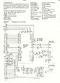
Z80 STI Schematic (1996)


How to build a RS232 - Interface for the CPC-Series!
Schematic and source code
First about the connection plan: You need a power supply that supports +9V,-9V and 5V. Connect all pins. You have to connect D0..D7 from the adressbus with the Z80 STI. You have to connect D0 with pin 21, D1 with pin 22, ..., D7 with pin 28. That's all. Now you can plug in the interface in the CPC. Switch the power on. If the CPC doesn't work normal please switch the power off and you have to watch for faults in the connection of your interface :-(. If everything is ok then you have to copy the assembler code and do the next test.
Bugs and Confusing things in the GIF schematic:
- Confusing: Signals 0..15 on the left side of the schematic refer to address lines A0..A15
- Bug: Z80-STI Pin 3 (TCO) should be wired to Pin 39 (RC), not to Pin 34 (A1).
Second part: How to program the interface. (The assembler code is saved in RS232.ASM)
Z80-STI: 50 to 19200 bps (5,6,7 or 8 bit, 1, 1 1/2, 2 stopbits, all parity flags) 24 registers, use 16 registers (direct) with F8E0-F8EF, the last 8 registers can be used indirect with a special register
The meaning and the Addresses of the registers
Register 0 (Port F8E0h) Indirect Data
This register transfers data from and to a indirect register.
Register 1 (Port F8E1h) Handshake signals
This register transfers the data from and to the I/O port of the chip. If you use V24 you can request handshake signals from this port. In this interface the following bits have this meaning:
Bit 0:    DTR (Data Terminal Ready)
Bit 1:    RTS (Ready to Send)
Bit 2:    CTS (Clear to Send)
Bit 3:    DSR (Data Set Ready)
Bit 4-7:  not used
These registers are used by the interrupt handler. If you want to know what you can do with this registers please write to Mostek for support.
Register 8 (Port F8E8h) Indirect Index
Bit 3-7 are used by the interrupt handler. With bit 0-2 you can choose the indirect register.
Register 9 (Port F8E9h) Timer Controls
Control register for timer A and B. You needn't to use the timer for a V24 interface.
Register 10 (Port F8EAh) Timer B
Timer B value
Register 11 (Port F8EBh) Timer A
Timer A value
Register 12 (Port F8ECh) Mode Control
USART-register. Change the connect-parameters.
       Bit   7     6     5     4     3     2     1     0
             x     x     x     x     x     x     x     0
             ^     ^     ^     ^     ^     ^     ^
             |     |     |     |     |     |     1=even
             |     |     |     |     |     |     0=odd
             |     |     |     |     |     1=Parity on
             |     |     |     |     |     0=Parity off
             |     |     |               Startbit  Stopbit  Format
             |     |     |     0     0 =    0         0     synchron
             |     |     |     0     1 =    1         1     asynchron
             |     |     |     1     0 =    1       1 1/2   asynchron
             |     |     |     1     1 =    1         2     asynchron
             |     0     0 = 8 Bit
             |     0     1 = 7 Bit
             |     1     0 = 6 Bit
             |     1     1 = 5 Bit
             please always set on 0
Register 13 (Port F8EDh) Rx Status
Receiver status. You need only the following bits:
Bit 0: Receiver-Enable, set to 1 if receiving is possible.
Bit 1: Memory full "1" or not "0". (If 8 Bits are
       received then the interface send memory full).
Register 14 (Port F8EEh) Tx Status
Sending status. Again you need only two bits:
Bit 0: Sending-Enable, must set to "1" if sending is allowed.
Bit 7: Memory full "1" or not "0". This bit can
       be used to ask if a word is send or not.
Register 15 (Port F8EFh) Rx/Tx Data
This is the send and receive register. Here you can get a word or send a word.
Indirect registers (Choose them with register 8)
register 0: Not used.
register 1: Data for Timer D.
register 2: Data for Timer C.
register 3: Not used.
register 4: Not used.
register 5: Not used.
register 6: I/O-Port (receive or send). High means sending, low receiving.
register 7: Used for Timer C and D. Reset with "1".
For more exact informations please write to Mostek and ask for support for the Z80-STI. You also can look at the assembler code.
About the assembler code
The program RS232.ASM installs 2 new BASIC commands (|FORMAT, |RECORD, |SEND). Here you can read the description about this new commands:
|FORMAT, number of bps, number of stop-bits, data bits, parity on/off, parity even/odd
Number of bps:       0 =   50 bps
                     1 =   75 bps
                     2 =  110 bps
                     3 =  150 bps
                     4 =  300 bps
                     5 =  600 bps
                     6 = 1200 bps
                     7 = 2400 bps

Number of stop bits: 1 = 1 stop bit
                     0 = 2 stop bit

Data bits:           0 = 7 data bits
                     1 = 8 data bits

Parity even/odd:     1 = even
                     0 = odd

Parity on/off:       1 = on
                     0 = off
Normally, you use 8N1 for connection with BBS's you can initialise this with |FORMAT, number of bps, 1, 1, 0, 1.
|RECORD, @a$ - The incoming chars will be read in a string. Control codes will be send to the string, too, because sometimes you need it for binary transmissions.
|SEND, @a$ - The string is send until it ends, except you press ESC. The program will not send CR or LF, so you can use this for binary transmission.
Used components:
- 1x Z80-STI (MK3801-4)
- 1x SN75189 - RS232 to TTL level shifter
- 1x SN75188 - TTL to RS232 level shifter
- 1x 74LS30 - Single 8-input NAND gate
- 1x 74LS138 - 1-of-8 inverting decoder/demultiplexer
- 1x 74LS20 - Dual 4-input NAND gates
- 1x 74LS04 - Hex Inverters
- 1x 74LS32 - Quad 2-input OR gates
- 1x 25pin SUB-D connector (male)
- 1x connector for the expansion port
Note: The 74LS20, 74LS04, 74LS32 are the smaller logic symbols in the schematic.
Note 2: The 74LS138 splits the address space to four regions (which is total nonsense), the 74LS20 is then merging them back to a single region (which is undoing that nonsense). Although the 74LS138 is rather useless in this case, the book from Paul Bauriedl contains further schematics, in which the 74LS138 does have some purpose.
Downloads
File:Rs232cpc.lzh - All info and files on topic