Difference between revisions of "765 FDC"
(→Motor On/Off Flipflop) |
m (→FDC Status Registers: typo) |
||
| Line 95: | Line 95: | ||
b0,1 US Unit Select (driveno during interrupt) | b0,1 US Unit Select (driveno during interrupt) | ||
| − | b2 HD Head | + | b2 HD Head Address (head during interrupt) |
b3 NR Not Ready (drive not ready or non-existing 2nd head selected) | b3 NR Not Ready (drive not ready or non-existing 2nd head selected) | ||
b4 EC Equipment Check (drive failure or recalibrate failed (retry)) | b4 EC Equipment Check (drive failure or recalibrate failed (retry)) | ||
| Line 104: | Line 104: | ||
Status Register 1 | Status Register 1 | ||
| − | b0 MA Missing | + | b0 MA Missing Address Mark (Sector_ID or DAM not found) |
b1 NW Not Writeable (tried to write/format disc with wprot_tab=on) | b1 NW Not Writeable (tried to write/format disc with wprot_tab=on) | ||
b2 ND No Data (Sector_ID not found, CRC fail in ID_field) | b2 ND No Data (Sector_ID not found, CRC fail in ID_field) | ||
Revision as of 22:41, 23 July 2016
µPD765 - Floppy Disc Controller (used in DDI-1 and CPC 664/6128).
- Port FA7Eh - Floppy Motor On/Off Flipflop
- Port FB7Eh - FDC 765 Main Status Register (read only)
- Port FB7Fh - FDC 765 Data Register (read/write)
Contents
IC Models used in CPC
More than one manufacturer made 765 compatible ICs. These are the ones known to be used in the CPC by looking at pictures of CPC mainboards. All should operate almost identically.
- Zilog Z0765A08PSC
- NEC D765AC-2
- NEC D765AC
- UMC UM8272A
The following data seperators are used:
- FDC9216
Accessing the FDC 765
The Data Register (Port FB7Fh) is used to write Commands and Parameters, to read/write data bytes, and to receive result bytes. These three operations are called Command-, Execution-, and Result-Phase. The Main Status Register signalizes when the FDC is ready to send/receive the next byte through the Data Register.
Command Phase A command consists of a command byte (eventually including the MF, MK, SK bits), and up to eight parameter bytes.
Execution Phase During this phase, the actual data is transferred (if any). Usually that are the data bytes for the read/written sector(s), except for the Format Track Command, in that case four bytes for each sector are transferred.
Result Phase Returns up to seven result bytes (depending on the command) that are containing status information. The Recalibrate and Seek Track commands do not return result bytes directly, instead the program must wait until the Main Status Register signalizes that the command has been completed, and then it must (!) send a Sense Interrupt State command to 'terminate' the Seek/Recalibrate command.
FDC Command Table
Command     Parameters              Exm Result               Description
02+MF+SK    HU TR HD ?? SZ NM GP SL <R> S0 S1 S2 TR HD NM SZ read track
03          XX YY                    -                       specify spd/dma
04          HU                       -  S3                   sense drive state
05+MT+MF    HU TR HD SC SZ LS GP SL <W> S0 S1 S2 TR HD LS SZ write sector(s)
06+MT+MF+SK HU TR HD SC SZ LS GP SL <R> S0 S1 S2 TR HD LS SZ read sector(s)
07          HU                       -                       recalib.seek TP=0
08          -                        -  S0 TP                sense int.state
09+MT+MF    HU TR HD SC SZ LS GP SL <W> S0 S1 S2 TR HD LS SZ wr deleted sec(s)
0A+MF       HU                       -  S0 S1 S2 TR HD LS SZ read ID
0C+MT+MF+SK HU TR HD SC SZ LS GP SL <R> S0 S1 S2 TR HD LS SZ rd deleted sec(s)
0D+MF       HU SZ NM GP FB          <W> S0 S1 S2 TR HD LS SZ format track
0F          HU TP                    -                       seek track n
11+MT+MF+SK HU TR HD SC SZ LS GP SL <W> S0 S1 S2 TR HD LS SZ scan equal
19+MT+MF+SK HU TR HD SC SZ LS GP SL <W> S0 S1 S2 TR HD LS SZ scan low or equal
1D+MT+MF+SK HU TR HD SC SZ LS GP SL <W> S0 S1 S2 TR HD LS SZ scan high or eq.
Parameter bits that can be specified in some Command Bytes are:
 MT  Bit7  Multi Track (continue multi-sector-function on other head)
 MF  Bit6  MFM-Mode-Bit (Default 1=Double Density)
 SK  Bit5  Skip-Bit (set if secs with deleted DAM shall be skipped)
Parameter/Result bytes are:
 HU  b0,1=Unit/Drive Number, b2=Physical Head Number, other bits zero
 TP  Physical Track Number
 TR  Track-ID (usually same value as TP)
 HD  Head-ID
 SC  First Sector-ID (sector you want to read)
 SZ  Sector Size (80h shl n) (default=02h for 200h bytes)
 LS  Last Sector-ID (should be same as SC when reading a single sector)
 GP  Gap (default=2Ah except command 0D: default=52h)
 SL  Sectorlen if SZ=0 (default=FFh)
 Sn  Status Register 0..3
 FB  Fillbyte (for the sector data areas) (default=E5h)
 NM  Number of Sectors (default=09h)
 XX  b0..3=headunload n*32ms (8" only), b4..7=steprate (16-n)*2ms
 YY  b0=DMA_disable, b1-7=headload n*4ms (8" only)
Format Track: output TR,HD,SC,SZ for each sector during execution phase Read Track: reads NM sectors (starting with first sec past index hole) Read ID: read ID bytes for current sec, repeated/undelayed read lists all IDs Recalib: walks up to 77 tracks, 80tr-drives may need second recalib if failed Seek/Recalib: All read/write commands will be disabled until succesful senseint Senseint: Set's IC if unsuccesful (no int has occured) (until IC=0)
FDC Status Registers
The Main Status register can be always read through Port FB7E. The other four Status Registers cannot be read directly, instead they are returned through the data register as result bytes in response to specific commands.
Main Status Register (Port FB7E)
 b0..3  DB  FDD0..3 Busy (seek/recalib active, until succesful sense intstat)
 b4     CB  FDC Busy (still in command-, execution- or result-phase)
 b5     EXM Execution Mode (still in execution-phase, non_DMA_only)
 b6     DIO Data Input/Output (0=CPU->FDC, 1=FDC->CPU) (see b7)
 b7     RQM Request For Master (1=ready for next byte) (see b6 for direction)
Status Register 0
 b0,1   US  Unit Select (driveno during interrupt)
 b2     HD  Head Address (head during interrupt)
 b3     NR  Not Ready (drive not ready or non-existing 2nd head selected)
 b4     EC  Equipment Check (drive failure or recalibrate failed (retry))
 b5     SE  Seek End (Set if seek-command completed)
 b6,7   IC  Interrupt Code (0=OK, 1=aborted:readfail/OK if EN, 2=unknown cmd
            or senseint with no int occured, 3=aborted:disc removed etc.)
Status Register 1
 b0     MA  Missing Address Mark (Sector_ID or DAM not found)
 b1     NW  Not Writeable (tried to write/format disc with wprot_tab=on)
 b2     ND  No Data (Sector_ID not found, CRC fail in ID_field)
 b3,6   0   Not used
 b4     OR  Over Run (CPU too slow in execution-phase (ca. 26us/Byte))
 b5     DE  Data Error (CRC-fail in ID- or Data-Field)
 b7     EN  End of Track (set past most read/write commands) (see IC)
Status Register 2
 b0     MD  Missing Address Mark in Data Field (DAM not found)
 b1     BC  Bad Cylinder (read/programmed track-ID different and read-ID = FF)
 b2     SN  Scan Not Satisfied (no fitting sector found)
 b3     SH  Scan Equal Hit (equal)
 b4     WC  Wrong Cylinder (read/programmed track-ID different) (see b1)
 b5     DD  Data Error in Data Field (CRC-fail in data-field)
 b6     CM  Control Mark (read/scan command found sector with deleted DAM)
 b7     0   Not Used
Status Register 3
 b0,1   US  Unit Select (pin 28,29 of FDC)
 b2     HD  Head Address (pin 27 of FDC)
 b3     TS  Two Side (0=yes, 1=no (!))
 b4     T0  Track 0 (on track 0 we are)
 b5     RY  Ready (drive ready signal)
 b6     WP  Write Protected (write protected)
 b7     FT  Fault (if supported: 1=Drive failure)
Motor On/Off Flipflop
Writing 00h to Port FA7Eh turns all disk drive motors off, writing 01h turns all motors on. It is not possible to turn on/off the motor of a specific drive separately. An exception are the Vortex F1-S, F1-D, M1-S and M1-D drives.
Notes
Before accessing a disk you should first "Recalibrate" the drive, that moves the head backwards until it reaches Track 0. (The Track 0 signal from the drive is sensed by the FDC and it initializes it's internal track counter for that drive to 0).
On a 80 track drive you may need to repeat that twice because some models of the FDC stop after 77 steps and if your recalibrating from track 80 it will not recalibrate fully.
Now if you want to format, read or write a sector on a specific track you must first Seek that track (command 0Fh). That'll move the read/write head to the physical track number. If you don't do that, then the FDC will attempt to read/write data to/from the current physical track, independenly of the specified logical Track-ID.
The Track-, Sector-, and Head-IDs are logical IDs only. These logical IDs are defined when formatting the disk, and aren't required to be identical to the physical Track, Sector, or Head numbers. However, when reading or writing a sector you must specify the same IDs that have been used during formatting.
Despite the confusing name, a sector with a "Deleted Data Address Mark" (DAM) is not deleted. The DAM-flag is just another ID-bit, and (if that ID-bit is specified correctly in the command) it can be read/written like normal data sectors.
At the end of a successful read/write command, the program should send a Terminal Count (TC) signal to the FDC. However, in the CPC the TC pin isn't connected to the I/O bus, making it impossible for the program to confirm a correct operation. For that reason, the FDC will assume that the command has failed, and it'll return both Bit 6 in Status Register 0 and Bit 7 in Status Register 1 set. The program should ignore this error message.
The CPC doesn't support floppy DMA transfers, and the FDCs Interrupt signal isn't used in the CPC also.
Usually single sided 40 Track 3" disk drives are used in CPCs, whereas 40 tracks is the official specification, practically 42 tracks could be used (the limit is specific to the FDD, some support more tracks. 42 is a good maximum). The FDC controller can be used to control 80 tracks, and/or double sided drives also, even though AMSDOS isn't supporting such formats. AMSDOS is supporting a maximum of two disk drives only.
Datasheets
- Media:UPD765 Datasheet OCRed.pdf - uPD765 disc controller
- Media:FDC9229BT Datasheet.pdf - FDC9229BT data separator (that usually assists the uPD765 chip)
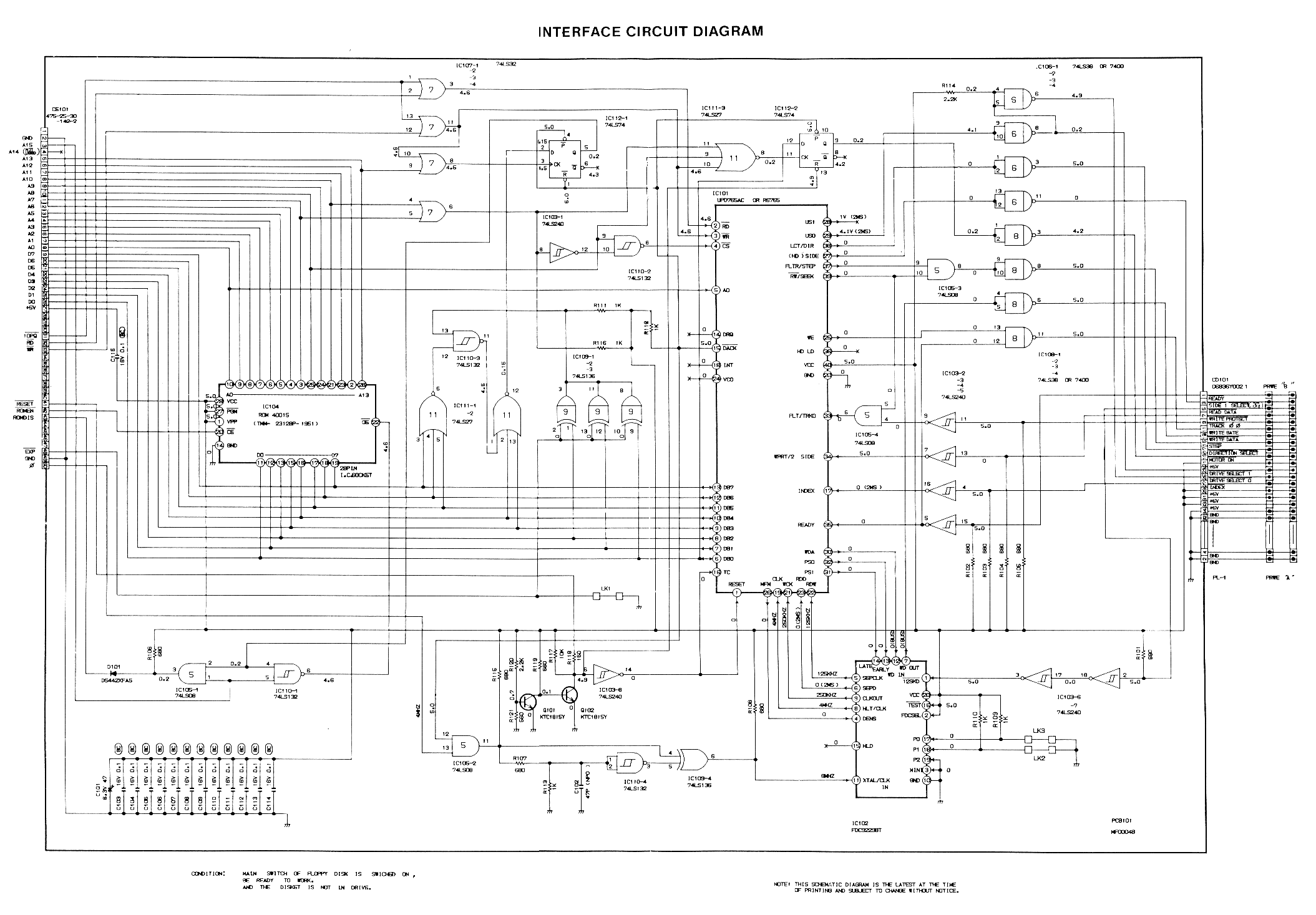
- Media:DDI Schematic.png - DDI-1 Schematic (disc interface for CPC464)