Difference between revisions of "Mainboard Versions"
From CPCWiki - THE Amstrad CPC encyclopedia!
(→CPC664) |
(→CPC664) |
||
| Line 51: | Line 51: | ||
[[File:German Schneider CPC664 open Gryzor missing edge.jpg|200px|left]] | [[File:German Schneider CPC664 open Gryzor missing edge.jpg|200px|left]] | ||
* '''Board: PT NO Z70205, MC0005B''' | * '''Board: PT NO Z70205, MC0005B''' | ||
| − | * Another 664 version, found in german Schneider CPCs ( | + | * Another 664 version, found in german Schneider CPCs (but might be also used in other countries?) |
| − | * This board version typically includes a small patch: A resistor soldered between Pin9 and Pin14 of IC105. The patch is also seen | + | * This board version typically includes a small patch: A resistor soldered between Pin9 (A0) and Pin14 (/CASADDR) of IC105. The patch is also seen [http://amstrad.cpc.free.fr/amstrad/cpc664_e.htm here]. The resistor is labeled as R160 in the schematic, but isn't labeled on the PCB, so it was apparently added after designing the PCB. |
<br style="clear:both;"> | <br style="clear:both;"> | ||
Revision as of 19:12, 9 April 2010
Contents
CPC464 version 1 (original)

- Board: PT NO Z70100, without any "MCnnnn" code, Copyright 1983
- Original version. Big mainboard, old Gate Array (with cooling plate). Real wires going to keyboard.

- Board: PT NO Z70100, MC0001A, Copyright 1983
- Keyboard connector now has two rows of soldering points (maybe intended to allow to use different connectors)

- Board: PT NO 270100, MC0001A, Copyright 1983
- This one is labelled 270100, not Z70100.
CPC464 version 2

- Board: PT NO Z70200, MC0002D, Copyright 1984
- Separate soldering points for old and new Gate Array (with changed pin-outs).
- Fragile plastic wires going to keyboard.
CPC464 version 3 (medium-sized)

- Board: PT NO Z70374, MC0044A
- Medium sized mainboard. Seems to be same as previous version, except that components are arranged more tightly.

- Board: PT NO Z70375, MC0044D
CPC464 version 4 (cost-down)

- Board: PT NO Z80329, MC0099A, Copyright 1988
- Tiny mainboard. Uses 100pin SMD Gate Array (combines the old Gate Array, CRTC, and some FDC/DRAM/RESET logic in one chip).
CPC664

- Board: PT NO Z70205, MC0005A
- 8pin FDC Data Separator

- Board: PT NO Z70205, MC0005B
- Another 664 version, found in german Schneider CPCs (but might be also used in other countries?)
- This board version typically includes a small patch: A resistor soldered between Pin9 (A0) and Pin14 (/CASADDR) of IC105. The patch is also seen here. The resistor is labeled as R160 in the schematic, but isn't labeled on the PCB, so it was apparently added after designing the PCB.
CPC6128 version 1

- Board: PT NO Z70210, MC0009A
- Separate soldering points for old and new Gate Array (as far as known, the old Gate Array was never used in 6128 though, only in 464).
- 8pin FDC Data Separator
CPC6128 version 2

- Board: PT NO Z70250
- Not sure if this version exists, maybe somebody just misread or mistyped the Z70290 board number (?)
CPC6128 version 3

- Board: PT NO Z70290, MC0020B, R1706-94HB, Copyright 1985
- Can be fitted with Amphenol connectors (done in germany) (instead Edge connectors). Uses 24pin FDC Data Separator.

- Board: PT NO Z70290, MC00201, 94V.0-FR-4, Copyright 1985
- Board: PT NO Z70290, MC0023D, 94HB-R1706, Copyright 1985
- Sold in germany, with Amphenol connectors (and dummy edge-connectors which don't have any contacts, and which are covered by green solder-stop layer), front of mainboard has several vias for giving better contact to shielding plate).
- Board: PT NO Z70290, MC...?, 94...?
- Looks almost like the above german board, but the "94HB-R1706" is different
- http://www.1000bit.it/scheda.asp?id=30 (not perfect picture quality; and board numbers are hidden under shielding plate and capacitors)
CPC6128 version 4 (cost-down)

- Board: PT NO Z80330 (1988)
- Uses 100pin SMD Gate Array (combines the old Gate Array and PAL, CRTC, and some FDC/DRAM/RESET logic in one chip).
- Can be fitted with four 64Kx4 RAM chips (or the normal sixteen 64Kx1 RAM chips)
- Printer port consists of 74LS174+74LS175 (instead of 74LS273)
CPC 464+

- Board: 2700-016P-3, MC0122D, Copyright 1990
- Same mainboard is used in 464+ and 664+ (though not all components installed in 464+, and with different LK Links. Uses 160pin SMD Gate Array (ASIC).
CPC 6128+
- Board: 2700-016P-3, MC0122D, Copyright 1990
- Same mainboard is used in 464+, but with additional components installed (extra RAM chips, FDC chips, Floppy connector, and with different LK Links).
- Uses 160pin SMD Gate Array (ASIC).
- Board: 2700-016P-3, MC0122B, Copyright 1990
- Another version, MC0122B, is shown in the Service Manuals (Plus series, page 5).
- Board: 2700-016P-3, MC0122A, Copyright 1990
- Yet another version, MC0122A, is shown in the Service Manuals (Plus series, page 16).
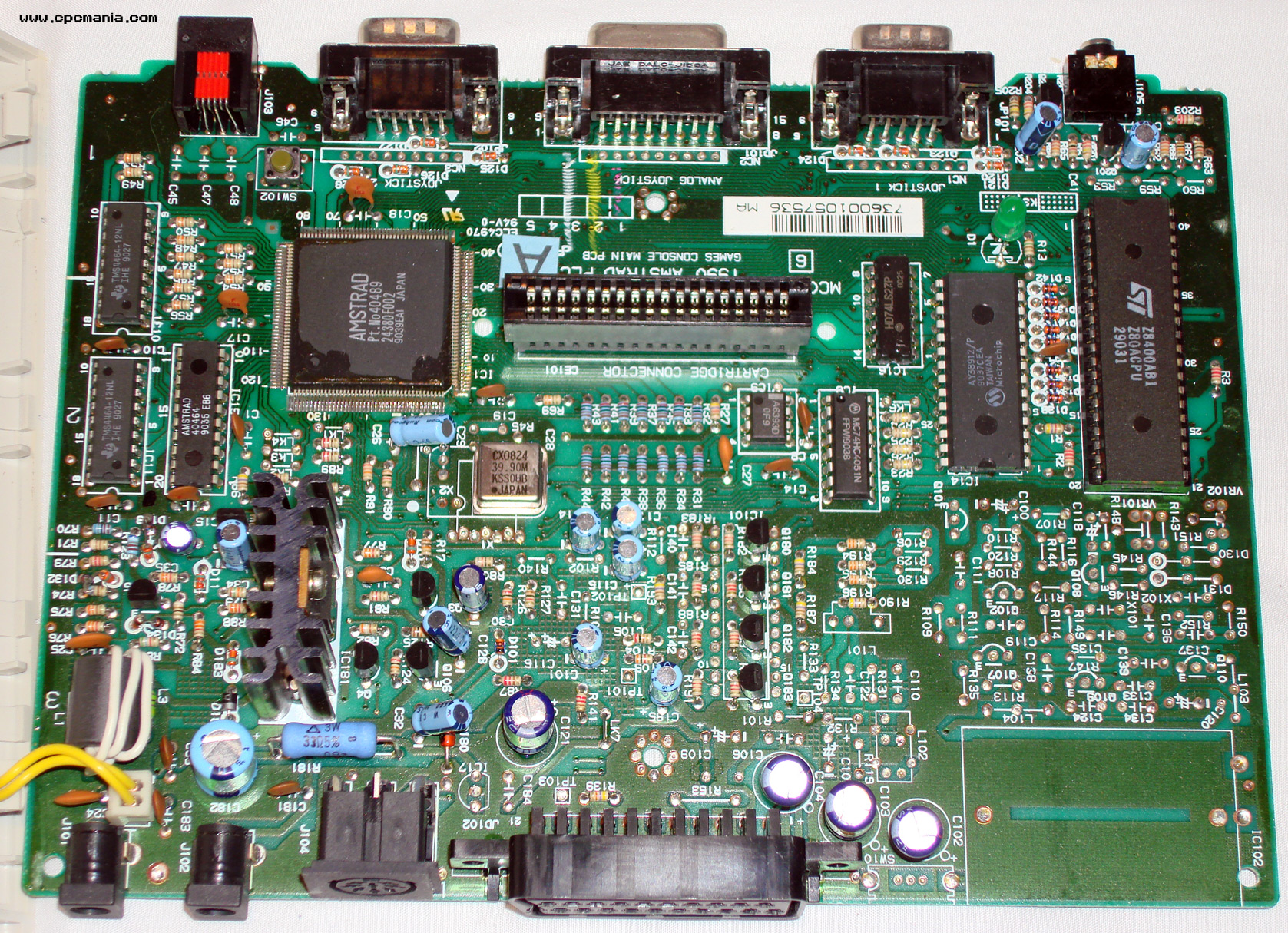
GX4000

- Board: 2700-017P-4, MC0123C, Copyright 1990
- Same chipset as CPC+, but lacks Keyboard, Expansion Port, Printer Port, Tape/Disc Interfaces.
- Additional Scart Connector and TV Modulator.
- Board: 27...?, MC...?, Copyright 1990
- Version without TV Modulator installed, and with IC101 replaced by 4 transistors.
- See this picture (might be same mainboard as above, not sure - the photo doesn't show the boards part number; hidden behind the cartridge slot, one thing that IS different is the K1 vs K3 text near the LED).
- Board: 2700-017P-3, MC0123A, Copyright 1990
- Shown in Service Manuals (Plus series, page 24 and page 32/france).
DDI-1

- Board: MF0004B, ISS3
- 20pin FDC Data Separator
- Photo of the above Board: MF0004B, ISS3 (and maybe other ISSues, if any?)
See also
- Amstrad part numbers - Part Numbers for PCBs and Chips
- Schematics
- Service Manuals - (cost-down 6128 is in the Amendment manual)