Mainboard Versions
From CPCWiki - THE Amstrad CPC encyclopedia!
Contents
CPC464 version 1 (original)

- Board: PT NO Z70100, without any "MCnnnn" code, Copyright 1983
- Original version. Big mainboard, old Gate Array (with cooling plate). Real wires going to keyboard.

- Board: PT NO Z70100, MC0001A, Copyright 1983
- Keyboard connector now has two rows of soldering points (maybe intended to allow to use different connectors)

- Board: PT NO 270100, MC0001A, Copyright 1983
- This one is labelled 270100, not Z70100.
CPC464 version 2

- Board: PT NO Z70200, MC0002D, Copyright 1984
- Separate soldering points for old and new Gate Array (with changed pin-outs).
- Fragile plastic wires going to keyboard.
CPC464 version 3 (medium-sized)

- Board: PT NO Z70374, MC0044A
- Medium sized mainboard. Seems to be same as previous version, except that components are arranged more tightly.

- Board: PT NO Z70375, MC0044D
CPC464 version 4 (cost-down)

- Board: PT NO Z80329, MC0099A, Copyright 1988
- Tiny mainboard. Uses 100pin SMD Gate Array (combines the old Gate Array, CRTC, and some FDC/DRAM/RESET logic in one chip).
CPC664

- Board: PT NO Z70205, MC0005A
- 8pin FDC Data Separator

- Board: PT NO Z70205, MC0005B
- Another 664 version, found in german Schneider CPCs (though it might be also used in other countries)
- This board version typically includes a small patch: A resistor soldered between Pin9 and Pin14 of IC105. The patch is also seen on http://amstrad.cpc.free.fr/amstrad/cpc664_e.htm. The resistor has no "R3NN" number on the text layer, so it was apparently added after designing the PCB.
CPC6128 version 1

- Board: PT NO Z70210, MC0009A
- Separate soldering points for old and new Gate Array (as far as known, the old Gate Array was never used in 6128 though, only in 464).
- 8pin FDC Data Separator
CPC6128 version 2

- Board: PT NO Z70250
- Not sure if this version exists, maybe somebody just misread or mistyped the Z70290 board number (?)
CPC6128 version 3

- Board: PT NO Z70290, MC0020B, R1706-94HB, Copyright 1985
- Can be fitted with Amphenol connectors (done in germany) (instead Edge connectors). Uses 24pin FDC Data Separator.

- Board: PT NO Z70290, MC00201, 94V.0-FR-4, Copyright 1985
- Board: PT NO Z70290, MC0023D, 94HB-R1706, Copyright 1985
- Sold in germany, with Amphenol connectors (and dummy edge-connectors which don't have any contacts, and which are covered by green solder-stop layer), front of mainboard has several vias for giving better contact to shielding plate).
- Board: PT NO Z70290, MC...?, 94...?
- Looks almost like the above german board, but the "94HB-R1706" is different
- http://www.1000bit.it/scheda.asp?id=30 (not perfect picture quality; and board numbers are hidden under shielding plate and capacitors)
CPC6128 version 4 (cost-down)

- Board: PT NO Z80330 (1988)
- Uses 100pin SMD Gate Array (combines the old Gate Array and PAL, CRTC, and some FDC/DRAM/RESET logic in one chip).
- Can be fitted with four 64Kx4 RAM chips (or the normal sixteen 64Kx1 RAM chips)
- Printer port consists of 74LS174+74LS175 (instead of 74LS273)
CPC 464+

- Board: 2700-016P-3, MC0122D, Copyright 1990
- Same mainboard is used in 464+ and 664+ (though not all components installed in 464+, and with different LK Links. Uses 160pin SMD Gate Array (ASIC).
CPC 6128+
- Board: 2700-016P-3, MC0122D, Copyright 1990
- Same mainboard is used in 464+, but with additional components installed (extra RAM chips, FDC chips, Floppy connector, and with different LK Links).
- Uses 160pin SMD Gate Array (ASIC).
- Board: 2700-016P-3, MC0122B, Copyright 1990
- Another version, MC0122B, is shown in the Service Manuals (Plus series, page 5).
- Board: 2700-016P-3, MC0122A, Copyright 1990
- Yet another version, MC0122A, is shown in the Service Manuals (Plus series, page 16).
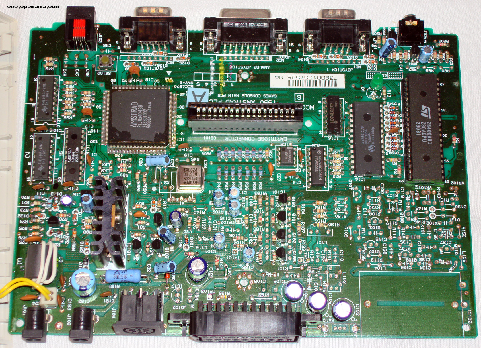
GX4000

- Board: 2700-017P-4, MC0123C, Copyright 1990
- Same chipset as CPC+, but lacks Keyboard, Expansion Port, Printer Port, Tape/Disc Interfaces.
- Additional Scart Connector and TV Modulator.
- Board: 27...?, MC...?, Copyright 1990
- Version without TV Modulator installed, and with IC101 replaced by 4 transistors.
- See this picture (might be same mainboard as above, not sure - the photo doesn't show the boards part number; hidden behind the cartridge slot, one thing that IS different is the K1 vs K3 text near the LED).
- Board: 2700-017P-3, MC0123A, Copyright 1990
- Shown in Service Manuals (Plus series, page 24 and page 32/france).
DDI-1

- Board: MF0004B, ISS3
- 20pin FDC Data Separator
- Photo of the above Board: MF0004B, ISS3 (and maybe other ISSues, if any?)
See also
- Amstrad part numbers - Part Numbers for PCBs and Chips
- Schematics
- Service Manuals - (cost-down 6128 is in the Amendment manual)