Difference between revisions of "Schneiderware"
(→I/O Ports) |
|||
| Line 11: | Line 11: | ||
* [[CPC Schneider International]] 12/1986, Page 124-130, Schneiderware #6 Uni-PIO (48 I/O lines) | * [[CPC Schneider International]] 12/1986, Page 124-130, Schneiderware #6 Uni-PIO (48 I/O lines) | ||
* [[CPC Schneider International]] 01/1987, Page 144, Advert | * [[CPC Schneider International]] 01/1987, Page 144, Advert | ||
| − | * [[CPC Schneider International]] 03/1987, Page 032-045, Schneiderware #7 | + | * [[CPC Schneider International]] 02/1987, Page ??-??, 7 MIDI Interface (not part of the Schneiderware series) |
| + | * [[CPC Schneider International]] 03/1987, Page 032-045, Schneiderware #7 A/D and/or D/A converter (?) | ||
* [[CPC Schneider International]] 04/1987, Page 026-034, Schneiderware #8 Eprom/RAM (EPROM and battery-back SRAM) | * [[CPC Schneider International]] 04/1987, Page 026-034, Schneiderware #8 Eprom/RAM (EPROM and battery-back SRAM) | ||
* [[CPC Schneider International]] 05/1987, Page 032-034, Notes (?) | * [[CPC Schneider International]] 05/1987, Page 032-034, Notes (?) | ||
Revision as of 14:14, 26 September 2010
The Schneiderware series consists of several DIY projects which have been released in german magazine CPC Schneider International published by DMV. The name "Schneiderware" was probably choosen due to its double meaning ("CPC Hardware" in computer language, or "specially fitted clothing" in german language). Aside from building the hardware on one's own, one could also order printed circuit boards, either fully assembled, or in kit form.
The various boards are having special connectors, intended to be mounted on the "Basisplatine" (some kind of a motherboard with ECB (Europe Card Bus) sockets) which allows to connect up to five Schneiderware boards to the CPCs Expansion Port; with some small modifications one could also connect the boards directly to the Expansion Port (the motherboard is merely an Y-cable-like adaptor without electrical components, so one doesn't really need it).
The DIY projects can be reportedly found in following issues (as by now, the magazine pages don't seem to be scanned, so details about I/O ports are unknown):
- CPC Schneider International 06/1986, Page 062-067, Schneiderware #1 Introduction (Theory)
- CPC Schneider International 07/1986, Page 060-067, Schneiderware #2 Basisplatine (Motherboard) & Centronics (Printer Port)
- CPC Schneider International 08/1986, Page 070-077, Schneiderware #3 V/24 (RS232 Interface)
- CPC Schneider International 09/1986, Page 078-083, Schneiderware #4 Netzteil (Power Supply)
- CPC Schneider International 10/1986, Page 078-085, Schneiderware #5 Echtzeituhr (Real Time Clock)
- CPC Schneider International 12/1986, Page 124-130, Schneiderware #6 Uni-PIO (48 I/O lines)
- CPC Schneider International 01/1987, Page 144, Advert
- CPC Schneider International 02/1987, Page ??-??, 7 MIDI Interface (not part of the Schneiderware series)
- CPC Schneider International 03/1987, Page 032-045, Schneiderware #7 A/D and/or D/A converter (?)
- CPC Schneider International 04/1987, Page 026-034, Schneiderware #8 Eprom/RAM (EPROM and battery-back SRAM)
- CPC Schneider International 05/1987, Page 032-034, Notes (?)
- CPC Schneider International 06/1987, Page 122-131, Schneiderware #9 Eprommer (EPROM Burner)
- CPC Schneider International 11/1987, Page 097-099, Notes (?)
Notes: The "Centronics" board is yet another 8bit Printer Port solution (but different than the joystick-signal based one that was released a few months earlier in the same magazine). The Real Time Clock is somewhat similar to the CPCI Real Time Clock released in a special issue of the same magazine, but not identical (the RTC chip has different pin-outs, and some of it's 4bit registers are working slightly different, the leap-year bits, for example).
Databoxes: UHR8000 RTC-RAM-driver in 10-1986 (hex listing, plus Hisoft Devpac source code) (caution this version uses incorrect I/O addresses FBE1-FBE3), UHRC000X RTC-ROM-driver in 4-1987 (this version uses correct I/O addresses FBE2-FBE4). Uni-PIO examples in 12-1986 (=only a few basic lines). There seem to be no Centronics and V/24 drivers included in databoxes.
I/O Ports
| Address (default) | Address (alternate) | Usage |
| F8E0h | F8F0h | Schneiderware Centronics 8255 PPI Port A (data) |
| F8E1h | F8F1h | Schneiderware Centronics 8255 PPI Port B (unused) |
| F8E2h | F8F2h | Schneiderware Centronics 8255 PPI Port C (busy/strobe) (bit7=busy, bit6-1=unused, bit0=strobe; strobe is externally inverted) (autolf is wired to GND, all other control/status signals are not connected) |
| F8E3h | F8F3h | Schneiderware Centronics 8255 PPI Control |
| F8E8h | F8F0h,F8F8h | Schneiderware Uni-PIO 8255 PPI #1 Port A (with pull-ups and red LEDs) |
| F8E9h | F8F1h,F8F9h | Schneiderware Uni-PIO 8255 PPI #1 Port B (with pull-ups and green LEDs) |
| F8EAh | F8F2h,F8FAh | Schneiderware Uni-PIO 8255 PPI #1 Port C (with pull-ups and red/green LEDs) |
| F8EBh | F8F3h,F8FBh | Schneiderware Uni-PIO 8255 PPI #1 Control |
| F8ECh | F8F4h,F8FCh | Schneiderware Uni-PIO 8255 PPI #2 Port A (without pull-ups or LEDs) |
| F8EDh | F8F5h,F8FDh | Schneiderware Uni-PIO 8255 PPI #2 Port B (without pull-ups or LEDs) |
| F8EEh | F8F6h,F8FEh | Schneiderware Uni-PIO 8255 PPI #2 Port C (without pull-ups or LEDs) |
| F8EFh | F8F7h,F8FFh | Schneiderware Uni-PIO 8255 PPI #2 Control |
| F9E0h | F9E2h | Schneiderware V/24 8251 USART Data |
| F9E1h | F9E3h | Schneiderware V/24 8251 USART Control |
| F9ECh | F9E8h | Schneiderware V/24 8253 Timer 0 (TX clock) |
| F9EDh | F9E9h | Schneiderware V/24 8253 Timer 1 (RX clock) |
| F9EEh | F9EAh | Schneiderware V/24 8253 Timer 2 (unused) |
| F9EFh | F9EBh | Schneiderware V/24 8253 Timer Control Note: Timer clock input is jumper select-able: 2MHz (default), or 1MHz |
| FAF0h | N/A | Schneiderware Eprom Burner 8255 PPI #1 Port A (Data, 8bit) |
| FAF1h | N/A | Schneiderware Eprom Burner 8255 PPI #1 Port B (Address LSBs, 8bit) |
| FAF2h | N/A | Schneiderware Eprom Burner 8255 PPI #1 Port C (Address MSBs, 7bit; bit7=unused) |
| FAF3h | N/A | Schneiderware Eprom Burner 8255 PPI #1 Control |
| FAF4h | N/A | Schneiderware Eprom Burner 8255 PPI #2 Port A (bit0-7=unused) |
| FAF5h | N/A | Schneiderware Eprom Burner 8255 PPI #2 Port B (bit0-5=unused, bit6=Red LED, bit7=Green LED) |
| FAF6h | N/A | Schneiderware Eprom Burner 8255 PPI #2 Port C (programming signals, 8bit) |
| FAF7h | N/A | Schneiderware Eprom Burner 8255 PPI #2 Control |
| FBE2h | BUGGED:FBE1h | Schneiderware RTC index/control (W) |
| FBE3h | BUGGED:FBE2h | Schneiderware RTC data 4bit (W) |
| FBE4h | BUGGED:FBE3h | Schneiderware RTC data 4bit (R) |
Pictures
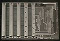
Schneiderware #2
Basisplatine (component side)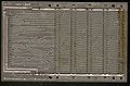
Schneiderware #2
Basisplatine (solder side)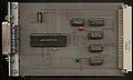
Schneiderware #2
Centronics (component side)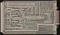
Schneiderware #2
Centronics (solder side)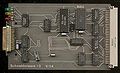
Schneiderware #3
V24 (component side)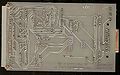
Schneiderware #3
V24 (solder side)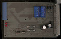
Schneiderware #4
Supply/Netzteil (component side) (incomplete?)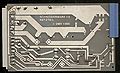
Schneiderware #4
Supply/Netzteil (solder side)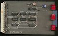
Schneiderware #5
RTC/Echtzeituhr (component side)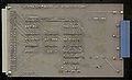
Schneiderware #5
RTC/Echtzeituhr (solder side)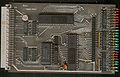
Schneiderware #6
Uni-PIO (component side)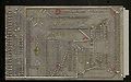
Schneiderware #6
Uni-PIO (solder side)
.jpg)
.jpg)
.jpg)
.jpg)
.jpg)
.jpg)
.jpg)
.jpg)
.jpg)
.jpg)
.jpg)
.jpg)
Datasheets
- M5832 Datasheet - Real time clock