Schneiderware Power Supply
The Schneiderware Power Supply is an external power supply published by german magazine CPC Schneider International as part of their Schneiderware DIY series. The plain PCB, or the fully assembled board were also available via mail-order.
Description
The power supply is needed only for Schneiderware projects that do require special voltages, or for projects that do overload the CPC's own +5V supply (which may happen when connection too many expansion boards, for example). The supply outputs the following voltages:
- +5V DC - needed only when the CPC's built-in supply gets overloaded
- +12V DC - needed for the Schneiderware V/24 interface and the Schneiderware Analog Converter
- -12V DC - needed for the Schneiderware V/24 interface only
- +24V DC - not used (was intended for the EPROM Burner, but when the EPROM burner was released, it contained a 5V-to-25V converter, and thus didn't need the +24V anymore)
Aside from the components on the PCB, one does also need a transformator, which isn't shown on the photos. Despite of being a very important component, the DIY article contained only few side-notes on the transformator. The thing must provide a number of AC voltages, and it might be difficult to find a matching transformator (one could get one from the magazine via mail-order, but it wasn't cheap).
Connection Cautions
The supply uses the same type of 2x32 pin connector as the other Schneiderware boards, however, the supply is NOT intended to be plugged into the ECB Bus sockets, instead, it should be wired to the 7 soldering points on the Schneiderware Basisplatine.
Namely, it connects to the three GND pins, and the 5V, and -/+12V pins. The seventh pin, "AC", is left unused (it's been intended for rechargeable "ACCU" batteries, but the later RTC and SRAM projects contained their own batteries, and didn't use the "AC" supply).
The CPC's internal +5V supply should be disconnected when connecting the external power-supply, otherwise something terrible might happen (for example, when one supply tries to output a few more volts than the other, or so).
Alternate Versions
There seem to have been one or two alternate versions:
- The photo in the magazine showed a different PCB with giant cooling plate, which won't fit on the DIY layout. That photo may have been a dummy/prototype.
- The magazine later released a correction on their letters page which recommended to replace the 5K6 and 10K resistors on the L200 voltage converter - it sounded perfectly reasonable - except that, the DIY project doesn't contain any of that components. The correction (if it wasn't total nonsense) implies that the magazine shipped different PCBs to some people via their mail-order service.
Article
- Schneiderware #4 Netzteil (Power Supply) (9/1986 pages 78-83, corrections on 10/1986 page 85, 5/1987 page 12)
Pictures
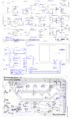
Power Supply Schematic
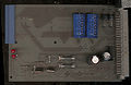
Supply/Netzteil (only +12V/-12V components installed)
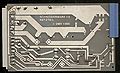
Supply/Netzteil (solder side)

.jpg)
.jpg)