Schneiderware Pseudo ROM
The Schneiderware Pseudo ROM is a expansion "ROM" board, with 16K EPROM (read-only) and 16K battery-backed SRAM (read/write-able), published by german magazine CPC Schneider International as part of their Schneiderware DIY series. The plain PCB, or the fully assembled board were also available via mail-order.
The ECB Bus connector of the board is intended to be plugged into the Schneiderware Basisplatine, but it could be also wired directly to the CPCs Expansion Port.
Contents
Software
The magazine article contains three listings with examples how to use the Pseudo ROM board, including a ROM version of the Schneiderware Real Time Clock driver.
Article
- Schneiderware #8 Pseudo ROM (SRAM and EPROM mapped as ROM) (4/1987 pages 26-34, plus corrections in 5/1987 pages 32-34)
I/O Ports
| Address (default) | Address (alternate) | Usage |
| DFxxh | N/A | Schneiderware RAM/EPROM - Expansion ROM bank number (W) Battery-backed SRAM and/or EPROM are selected when the bank-number matches the jumper-selected values; the memory is then mapped to C000h..FFFFh (in case of READing one must also enable upper ROM via Gate Array). The bank number decoding is a bit strange:
The SRAM/Write mode doesn't disable the internal RAM in the CPC, so writes are going both to SRAM and normal RAM at C000-FFFF, that no matter if upper ROM is enabled/disabled via Gate Array; the author recommended to map VRAM to 4000-7FFF via CRTC registers, in order to prevent video dirt during writing. |
Pictures
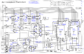
SRAM/EPROM Schematic
