Difference between revisions of "Schneiderware V/24 Interface"
(→I/O Ports) |
|||
| (6 intermediate revisions by one other user not shown) | |||
| Line 2: | Line 2: | ||
The [[ECB Bus]] connector of the board is intended to be plugged into the [[Schneiderware Basisplatine]], but it could be also wired directly to the CPCs Expansion Port. The V/24 board additionally requires a [[Schneiderware Power Supply]] (or another external power supply with +12V/-12V). | The [[ECB Bus]] connector of the board is intended to be plugged into the [[Schneiderware Basisplatine]], but it could be also wired directly to the CPCs Expansion Port. The V/24 board additionally requires a [[Schneiderware Power Supply]] (or another external power supply with +12V/-12V). | ||
| − | |||
| − | |||
== I/O Ports == | == I/O Ports == | ||
| Line 25: | Line 23: | ||
|- | |- | ||
|} | |} | ||
| + | |||
| + | == Jumper Problems == | ||
'''Caution''' - The '''clock source''' can be jumpered to 2MHz (default), or to 1MHz. Moreover, the '''handshaking''' signals (CTS/RTS, DTR/DSR) can be disabled via jumpers. There is no good reason for using the 1MHz setting, nor for disabling handshaking at hardware level - these features are only "good" for provoking compatibility problems with software that expects the jumpers to be set to this or that position. | '''Caution''' - The '''clock source''' can be jumpered to 2MHz (default), or to 1MHz. Moreover, the '''handshaking''' signals (CTS/RTS, DTR/DSR) can be disabled via jumpers. There is no good reason for using the 1MHz setting, nor for disabling handshaking at hardware level - these features are only "good" for provoking compatibility problems with software that expects the jumpers to be set to this or that position. | ||
| − | For the more bizarre part, the handshaking signals are '''disabled''' by default. And, these pre-defined settings are implemented as '''hardwired''' connections on the '''component''' side of the PCB; meaning that one cannot cut these connections once when the components (jumpers) are installed on the PCB. | + | For the more bizarre part, the handshaking signals are '''disabled''' by default. And, these pre-defined settings are implemented as '''hardwired''' connections on the '''component''' side of the PCB; meaning that one cannot cut these connections once when the components (jumpers) are installed on the PCB. About 15 months later, in issue 11-1987, the author did admit that they shipped fully assembled PCBs without cutting these "hidden" connections underneath of the jumpers. |
| + | |||
| + | Aside from that, both the PCB and the original schematic haven't been too clear about which pins on the 4-pin jumpers should be connected together (and which of the predefined horizontal & vertical connections should be disconnected). Without good reverse-engineering skills it's been rather frustating (if not impossible) to find the correct jumper settings. | ||
== Pictures == | == Pictures == | ||
| Line 37: | Line 39: | ||
File:Schneiderware 3 V24 (solder side).jpg|V/24 (solder side) | File:Schneiderware 3 V24 (solder side).jpg|V/24 (solder side) | ||
</gallery> | </gallery> | ||
| + | |||
| + | == Scanned Article == | ||
| + | |||
| + | * [[Media:Schneiderware 3 - Serial V24 Interface.pdf|Schneiderware 3 - Serial V24 Interface.pdf]] - RS232 Interface - '''8/1986 page 70-77''', plus correction from 9/1986 page 80, final notes from 11/1987 page 98 | ||
| + | |||
| + | == Datasheets == | ||
| + | |||
| + | * [[Media:8251.pdf|8251 Datasheet]] - older 8251 datasheet (pin-outs only, without programming info) | ||
| + | * [[Media:8251A.pdf|8251A Datasheet]] - newer 8251A datasheet (detailed info) | ||
| + | * [[Media:8253.pdf|8253 Datasheet]] - 8253 Timer Datasheet (slower clock, write-only control registers) | ||
| + | * [[Media:8254.pdf|8254 Datasheet]] - 8254 Timer Datasheet (faster clock, read/write-able control registers, otherwise compatible with 8253) | ||
| + | |||
| + | [[Category:Peripherals]] | ||
Latest revision as of 03:19, 29 August 2014
The Schneiderware V/24 Interface is a RS232 Interface, published by german magazine CPC Schneider International as part of their Schneiderware DIY series. The plain PCB, or the fully assembled board were also available via mail-order.
The ECB Bus connector of the board is intended to be plugged into the Schneiderware Basisplatine, but it could be also wired directly to the CPCs Expansion Port. The V/24 board additionally requires a Schneiderware Power Supply (or another external power supply with +12V/-12V).
I/O Ports
Default I/O Addresses are F9E0h-F8E1h and F9ECh-F9EFh (ie. the lowest and highest addresses in the F9E0h-F9EFh region). Alternately, addresses F9E2h-F8E3h and F9E8h-F9EBh (ie. the middle addresses in the F9E0h-F9EFh region) are jumper select-able (intended to allow to connect two RS232 cards to the computer).
| Address (default) | Address (alternate) | Usage |
| F9E0h | F9E2h | Schneiderware V/24 8251 USART chip Data |
| F9E1h | F9E3h | Schneiderware V/24 8251 USART chip Control |
| F9ECh | F9E8h | Schneiderware V/24 8253 chip Timer 0 (TX clock) |
| F9EDh | F9E9h | Schneiderware V/24 8253 chip Timer 1 (RX clock) |
| F9EEh | F9EAh | Schneiderware V/24 8253 chip Timer 2 (unused) |
| F9EFh | F9EBh | Schneiderware V/24 8253 chip Timer Control |
Jumper Problems
Caution - The clock source can be jumpered to 2MHz (default), or to 1MHz. Moreover, the handshaking signals (CTS/RTS, DTR/DSR) can be disabled via jumpers. There is no good reason for using the 1MHz setting, nor for disabling handshaking at hardware level - these features are only "good" for provoking compatibility problems with software that expects the jumpers to be set to this or that position.
For the more bizarre part, the handshaking signals are disabled by default. And, these pre-defined settings are implemented as hardwired connections on the component side of the PCB; meaning that one cannot cut these connections once when the components (jumpers) are installed on the PCB. About 15 months later, in issue 11-1987, the author did admit that they shipped fully assembled PCBs without cutting these "hidden" connections underneath of the jumpers.
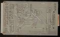
Aside from that, both the PCB and the original schematic haven't been too clear about which pins on the 4-pin jumpers should be connected together (and which of the predefined horizontal & vertical connections should be disconnected). Without good reverse-engineering skills it's been rather frustating (if not impossible) to find the correct jumper settings.
Pictures

V/24 Schematic
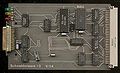
V/24 (component side)
V/24 (solder side)

.jpg)
.jpg)
Scanned Article
- Schneiderware 3 - Serial V24 Interface.pdf - RS232 Interface - 8/1986 page 70-77, plus correction from 9/1986 page 80, final notes from 11/1987 page 98
Datasheets
- 8251 Datasheet - older 8251 datasheet (pin-outs only, without programming info)
- 8251A Datasheet - newer 8251A datasheet (detailed info)
- 8253 Datasheet - 8253 Timer Datasheet (slower clock, write-only control registers)
- 8254 Datasheet - 8254 Timer Datasheet (faster clock, read/write-able control registers, otherwise compatible with 8253)