Difference between revisions of "Sideways ram"
m (New page: The Sideways RAM unit, developed by Paul Townsend, comprises 128K of static RAM and an interface to the Amstrad computers, allowing software destined for sideways ROM to be developed easil...) |
(→Downloads) |
||
| (10 intermediate revisions by 4 users not shown) | |||
| Line 1: | Line 1: | ||
The Sideways RAM unit, developed by Paul Townsend, comprises 128K of static RAM and an interface to the Amstrad computers, allowing software destined for sideways ROM to be developed easily. | The Sideways RAM unit, developed by Paul Townsend, comprises 128K of static RAM and an interface to the Amstrad computers, allowing software destined for sideways ROM to be developed easily. | ||
| − | |||
| − | |||
It wasn't so much "bought" as a workable unit, but was designed and built by Paul himself, inspired by the scrapping of the original RAM board. The interface logic between the CPC and the original RAM chips, was all his own design. | It wasn't so much "bought" as a workable unit, but was designed and built by Paul himself, inspired by the scrapping of the original RAM board. The interface logic between the CPC and the original RAM chips, was all his own design. | ||
| − | |||
| − | |||
Essentially it was a "soft" version of an 8-chip ROM board, a development aid for ROM-based software. At the time Paul was developing a ROM-based word processor for the CPC. Not having PROM burning facilities at home, this unit was ideal because new versions could be assembled, tested, debugged and developed further while reproducing the target architecture. | Essentially it was a "soft" version of an 8-chip ROM board, a development aid for ROM-based software. At the time Paul was developing a ROM-based word processor for the CPC. Not having PROM burning facilities at home, this unit was ideal because new versions could be assembled, tested, debugged and developed further while reproducing the target architecture. | ||
| − | |||
| − | |||
In the end, it proved more reliable than a true ROM board since there were no hardware contacts to go haywire (though there were software bugs). Paul ended up using that exclusively, loading up a standard configuration into the sideways RAM with different ROMs, along with Maxam and Utopia, with Oddjob, BCPL, Toolkit and a few others to hand if required. | In the end, it proved more reliable than a true ROM board since there were no hardware contacts to go haywire (though there were software bugs). Paul ended up using that exclusively, loading up a standard configuration into the sideways RAM with different ROMs, along with Maxam and Utopia, with Oddjob, BCPL, Toolkit and a few others to hand if required. | ||
| − | |||
| − | |||
| − | <br> | + | <br> |
| − | + | ||
| − | == | + | == Schematics == |
Sideways RAM schematics: | Sideways RAM schematics: | ||
| − | + | <gallery> | |
| − | + | Image:SidewaysRamBoard.jpg|Sideways Ram Board | |
| + | Image:SidewaysRamSchems1.jpg|Sideways Ram Schematics | ||
| + | Image:SidewaysRamSchems2.jpg|Sideways Ram Schematics | ||
| + | Image:SidewaysRamSchems3.jpg|Sideways Ram Schematics | ||
| + | Image:SidewaysRamSchems4.jpg|Sideways Ram Schematics | ||
| + | Image:SidewaysRamSchems5.jpg|Sideways Ram Schematics | ||
| + | </gallery> | ||
| − | + | == Downloads == | |
| − | + | * [[File:SidewaysRam.rar|Sideways Ram Manual]] | |
| − | + | * [[File:SidewaysRamSoftware.rar|Sideways Ram Software]] | |
| − | + | * [[File:SidewaysRamListing.rar|Sideways Ram Listing]] | |
| − | + | ||
| − | + | ||
| − | + | [[Category:Peripherals]][[Category:Expansion ROM]] | |
| − | + | ||
| − | + | ||
| − | + | ||
| − | + | ||
| − | + | ||
| − | + | ||
| − | + | ||
| − | + | ||
| − | + | ||
| − | + | ||
| − | + | ||
| − | + | ||
| − | + | ||
| − | + | ||
| − | + | ||
| − | + | ||
| − | + | ||
| − | + | ||
| − | + | ||
| − | + | ||
| − | + | ||
| − | + | ||
| − | + | ||
| − | + | ||
| − | + | ||
| − | + | ||
| − | + | ||
| − | + | ||
| − | + | ||
| − | + | ||
| − | + | ||
| − | + | ||
| − | + | ||
| − | + | ||
| − | + | ||
| − | + | ||
Latest revision as of 06:18, 11 March 2018
The Sideways RAM unit, developed by Paul Townsend, comprises 128K of static RAM and an interface to the Amstrad computers, allowing software destined for sideways ROM to be developed easily.
It wasn't so much "bought" as a workable unit, but was designed and built by Paul himself, inspired by the scrapping of the original RAM board. The interface logic between the CPC and the original RAM chips, was all his own design.
Essentially it was a "soft" version of an 8-chip ROM board, a development aid for ROM-based software. At the time Paul was developing a ROM-based word processor for the CPC. Not having PROM burning facilities at home, this unit was ideal because new versions could be assembled, tested, debugged and developed further while reproducing the target architecture.
In the end, it proved more reliable than a true ROM board since there were no hardware contacts to go haywire (though there were software bugs). Paul ended up using that exclusively, loading up a standard configuration into the sideways RAM with different ROMs, along with Maxam and Utopia, with Oddjob, BCPL, Toolkit and a few others to hand if required.
Schematics
Sideways RAM schematics:
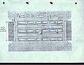
Sideways Ram Board

Sideways Ram Schematics

Sideways Ram Schematics

Sideways Ram Schematics
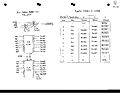
Sideways Ram Schematics

Sideways Ram Schematics


