Difference between revisions of "Gate Array"
(→Note) |
m (→To calculate the colour value) |
||
| (28 intermediate revisions by 6 users not shown) | |||
| Line 9: | Line 9: | ||
In the CPC+ system, the functions of the Gate-Array are integrated into a single [[ASIC|ASIC]]. When the ASIC is "locked", the extra features are not available and the ASIC operates the same as the Gate-Array in the CPC allowing programs written for the CPC to work on the Plus without modification. The ASIC must be "un-locked" to access the new features. | In the CPC+ system, the functions of the Gate-Array are integrated into a single [[ASIC|ASIC]]. When the ASIC is "locked", the extra features are not available and the ASIC operates the same as the Gate-Array in the CPC allowing programs written for the CPC to work on the Plus without modification. The ASIC must be "un-locked" to access the new features. | ||
| − | In the [[KC Compact]] system, the functions of the Gate-Array are "emulated" in [[ | + | In the [[KC Compact]] system, the functions of the Gate-Array are "emulated" in TTL chips, [[CIO Overview|CIO]], and its color translation EPROM. |
In the "cost-down" version of the CPC6128, the functions of the Gate-Array are integrated into a ASIC. | In the "cost-down" version of the CPC6128, the functions of the Gate-Array are integrated into a ASIC. | ||
| Line 29: | Line 29: | ||
{|{{Prettytable|width: 700px; font-size: 2em;}} | {|{{Prettytable|width: 700px; font-size: 2em;}} | ||
|- | |- | ||
| − | |''Bit 7''||''Bit 6''||''Function'' | + | |''Data Bit 7''||''Data Bit 6''||''Function'' |
|- | |- | ||
| 0 || 0 || Select pen | | 0 || 0 || Select pen | ||
| Line 43: | Line 43: | ||
===== Note ===== | ===== Note ===== | ||
| − | This function is not available in the Gate-Array, but is performed by a device at the same I/O port address location. In the CPC464, CPC664 and KC compact, this function is performed in a memory-expansion (e.g. Dk'Tronics 64K RAM Expansion), if this expansion is not present then the function is not available. In the CPC6128, this function is performed by a PAL located on the main PCB, or a memory-expansion. In the 464+ and 6128+ this function is performed by the ASIC or a memory expansion. Please read the document on RAM management for more information. | + | This function is not available in the Gate-Array, but is performed by a device at the same I/O port address location. In the CPC464, CPC664 and KC compact, this function is performed in a memory-expansion (e.g. Dk'Tronics 64K RAM Expansion), if this expansion is not present then the function is not available. In the CPC6128, this function is performed by a [[PAL16L8|PAL]] located on the main PCB, or a memory-expansion. In the 464+ and 6128+ this function is performed by the ASIC or a memory expansion. Please read the document on RAM management for more information. |
| − | == | + | == Register 0 - Palette Index (Pen selection) == |
When bit 7 and bit 6 are set to "0", the remaining bits determine which pen is to have its colour changed. When bit 4 is set to "0", bits 3 to 0 define which pen is to be selected. When bit 4 is set to "1", the value contained in bits 3-0 is ignored and the border is selected. | When bit 7 and bit 6 are set to "0", the remaining bits determine which pen is to have its colour changed. When bit 4 is set to "0", bits 3 to 0 define which pen is to be selected. When bit 4 is set to "1", the value contained in bits 3-0 is ignored and the border is selected. | ||
| Line 53: | Line 53: | ||
Each mode has a fixed number of pens. Mode 0 has 16 pens, mode 1 has 4 pens and mode 2 has 2 pens. | Each mode has a fixed number of pens. Mode 0 has 16 pens, mode 1 has 4 pens and mode 2 has 2 pens. | ||
| − | + | === Summary === | |
{|{{Prettytable|width: 700px; font-size: 2em;}} | {|{{Prettytable|width: 700px; font-size: 2em;}} | ||
| Line 99: | Line 99: | ||
|} | |} | ||
| − | == | + | == Register 1 - Palette Data (Colour selection) == |
Once the pen has been selected its colour can then be changed. Bits 4 to 0 specify the hardware colour number from the hardware colour palette. | Once the pen has been selected its colour can then be changed. Bits 4 to 0 specify the hardware colour number from the hardware colour palette. | ||
| Line 105: | Line 105: | ||
Even though there is provision for 32 colours, only 27 are possible. The remaining colours are duplicates of those already in the colour palette. | Even though there is provision for 32 colours, only 27 are possible. The remaining colours are duplicates of those already in the colour palette. | ||
| − | + | === Summary === | |
{|{{Prettytable|width: 700px; font-size: 2em;}} | {|{{Prettytable|width: 700px; font-size: 2em;}} | ||
| Line 128: | Line 128: | ||
|} | |} | ||
| − | == | + | == Register 2 - Select screen mode and ROM configuration == |
| − | + | ||
| − | + | ||
| − | + | ||
| − | + | ||
| − | + | ||
| − | + | ||
| − | + | ||
| − | + | ||
| − | + | ||
| − | + | ||
| − | + | ||
| − | + | ||
| − | + | ||
| − | + | ||
| − | + | ||
| − | + | ||
| − | + | ||
| − | + | ||
| − | + | ||
| − | + | ||
| − | + | ||
| − | + | ||
| − | + | ||
| − | + | ||
| − | + | ||
| − | + | ||
| − | + | ||
| − | + | ||
| − | + | ||
| − | + | ||
| − | + | ||
| − | + | ||
| − | + | ||
| − | + | ||
| − | + | ||
| − | + | ||
| − | + | ||
| − | + | ||
| − | + | ||
| − | + | ||
| − | + | ||
| − | + | ||
| − | + | ||
| − | + | ||
| − | + | ||
| − | + | ||
| − | + | ||
| − | + | ||
| − | + | ||
| − | + | ||
| − | + | ||
| − | + | ||
| − | + | ||
| − | + | ||
| − | + | ||
| − | + | ||
| − | + | ||
| − | + | ||
| − | + | ||
| − | + | ||
| − | + | ||
| − | + | ||
| − | + | ||
| − | + | ||
| − | + | ||
| − | + | ||
| − | + | ||
| − | + | ||
| − | + | ||
| − | + | ||
| − | + | ||
| − | + | ||
| − | + | ||
| − | + | ||
| − | + | ||
| − | + | ||
| − | + | ||
| − | + | ||
| − | + | ||
| − | + | ||
| − | + | ||
| − | + | ||
| − | + | ||
| − | + | ||
| − | + | ||
| − | + | ||
| − | + | ||
| − | + | ||
| − | + | ||
| − | + | ||
| − | + | ||
| − | + | ||
| − | + | ||
| − | + | ||
| − | + | ||
| − | + | ||
| − | + | ||
| − | + | ||
| − | + | ||
| − | + | ||
| − | + | ||
| − | + | ||
| − | + | ||
| − | + | ||
| − | + | ||
| − | + | ||
| − | + | ||
| − | + | ||
| − | + | ||
| − | + | ||
| − | + | ||
| − | + | ||
| − | + | ||
| − | + | ||
| − | + | ||
| − | + | ||
| − | + | ||
| − | + | ||
| − | + | ||
| − | + | ||
| − | + | ||
| − | + | ||
| − | + | ||
| − | + | ||
| − | + | ||
| − | + | ||
| − | + | ||
| − | + | ||
| − | + | ||
| − | + | ||
| − | + | ||
| − | + | ||
| − | + | ||
| − | + | ||
| − | + | ||
| − | + | ||
| − | + | ||
| − | + | ||
| − | + | ||
| − | + | ||
| − | + | ||
This is a general purpose register responsible for the [[Video modes|screen mode]] and the ROM configuration. | This is a general purpose register responsible for the [[Video modes|screen mode]] and the ROM configuration. | ||
| − | + | === Screen mode selection === | |
The function of bits 1 and 0 is to define the screen mode. The settings for bits 1 and 0 and the corresponding screen mode are given in the table below. | The function of bits 1 and 0 is to define the screen mode. The settings for bits 1 and 0 and the corresponding screen mode are given in the table below. | ||
| Line 294: | Line 153: | ||
Mode changing is synchronised with HSYNC. If the mode is changed, it will take effect from the next HSYNC. | Mode changing is synchronised with HSYNC. If the mode is changed, it will take effect from the next HSYNC. | ||
| − | + | === ROM configuration selection === | |
Bit 2 is used to enable or disable the lower ROM area. The lower ROM area occupies memory addresses &0000-&3fff and is used to access the operating system ROM. When the lower ROM area is is enabled, reading from &0000-&3FFF will return data in the ROM. When a value is written to &0000-&3FFF, it will be written to the RAM underneath the RAM. When it is disabled, data read from &0000-&3FFF will return the data in the RAM. | Bit 2 is used to enable or disable the lower ROM area. The lower ROM area occupies memory addresses &0000-&3fff and is used to access the operating system ROM. When the lower ROM area is is enabled, reading from &0000-&3FFF will return data in the ROM. When a value is written to &0000-&3FFF, it will be written to the RAM underneath the RAM. When it is disabled, data read from &0000-&3FFF will return the data in the RAM. | ||
| Line 302: | Line 161: | ||
Bit 4 controls the interrupt generation. It can be used to delay interrupts. See the document on interrupt generation for more information. | Bit 4 controls the interrupt generation. It can be used to delay interrupts. See the document on interrupt generation for more information. | ||
| − | + | === Summary === | |
{|{{Prettytable|width: 700px; font-size: 2em;}} | {|{{Prettytable|width: 700px; font-size: 2em;}} | ||
| Line 324: | Line 183: | ||
| 0 || x | | 0 || x | ||
|} | |} | ||
| + | |||
| + | == Register 3 - RAM Banking == | ||
| + | |||
| + | This register exists only in CPCs with 128K RAM (like the CPC 6128, or CPCs with [[Standard Memory Expansions]]). Note: In the CPC 6128, the register is a separate PAL that assists the Gate Array chip. | ||
| + | |||
| + | {|{{Prettytable|width: 700px; font-size: 2em;}} | ||
| + | |- | ||
| + | | ''Bit'' || ''Value'' || ''Function'' | ||
| + | |- | ||
| + | | 7 || 1 || rowspan="2" | Gate Array function 3 | ||
| + | |- | ||
| + | | 6 || 1 | ||
| + | |- | ||
| + | | 5 || b || rowspan="3" |64K bank number (0..7); always 0 on an unexpanded CPC6128, 0-7 on [[Standard Memory Expansions]] | ||
| + | |- | ||
| + | | 4 || b | ||
| + | |- | ||
| + | | 3 || b | ||
| + | |- | ||
| + | | 2 || x || rowspan="3" | RAM Config (0..7) | ||
| + | |- | ||
| + | | 1 || x | ||
| + | |- | ||
| + | | 0 || x | ||
| + | |} | ||
| + | |||
| + | |||
| + | The 3bit RAM Config value is used to access the second 64K of the total 128K RAM that is built into the CPC 6128 or the additional 64K-512K of standard memory expansions. These contain up to eight 64K ram banks, which are selected with bit 3-5. A standard CPC 6128 only contains bank 0. Normally the register is set to 0, so that only the first 64K RAM are used (identical to the CPC 464 and 664 models). The register can be used to select between the following eight predefined configurations only: | ||
| + | |||
| + | -Address- 0 1 2 3 4 5 6 7 | ||
| + | 0000-3FFF RAM_0 RAM_0 RAM_4 RAM_0 RAM_0 RAM_0 RAM_0 RAM_0 | ||
| + | 4000-7FFF RAM_1 RAM_1 RAM_5 RAM_3 RAM_4 RAM_5 RAM_6 RAM_7 | ||
| + | 8000-BFFF RAM_2 RAM_2 RAM_6 RAM_2 RAM_2 RAM_2 RAM_2 RAM_2 | ||
| + | C000-FFFF RAM_3 RAM_7 RAM_7 RAM_7 RAM_3 RAM_3 RAM_3 RAM_3 | ||
| + | |||
| + | The Video RAM is always located in the first 64K, VRAM is in no way affected by this register. | ||
== Programming the Gate Array - Examples == | == Programming the Gate Array - Examples == | ||
| Line 343: | Line 238: | ||
RET | RET | ||
</pre> | </pre> | ||
| − | === | + | |
| + | === Misc === | ||
The hardware colour number is different to the colour range used by the firmware, so a conversion chart is provided for the corresponding firmware/hardware colour values and the corresponding colour name. | The hardware colour number is different to the colour range used by the firmware, so a conversion chart is provided for the corresponding firmware/hardware colour values and the corresponding colour name. | ||
| − | + | === Note === | |
The firmware keeps track of the colours it is using. Every VSYNC (assuming interrupts are enabled) the firmware sets the colours. This enables the user to have flashing colours. If the user selects a new colour using the gate array, the new colour will flash temporarily and then return to its original colour. This is due to the firmware resetting the colour. When using the firmware, use its routines to select the colour, and the colour will remain. | The firmware keeps track of the colours it is using. Every VSYNC (assuming interrupts are enabled) the firmware sets the colours. This enables the user to have flashing colours. If the user selects a new colour using the gate array, the new colour will flash temporarily and then return to its original colour. This is due to the firmware resetting the colour. When using the firmware, use its routines to select the colour, and the colour will remain. | ||
| − | Example: | + | Example: [For whatever reason, this example does NOT refer to the above firmware stuff] |
<pre>ld bc,7f00+1 ;Gate array function (set pen) | <pre>ld bc,7f00+1 ;Gate array function (set pen) | ||
;and pen number | ;and pen number | ||
| Line 362: | Line 258: | ||
</pre> | </pre> | ||
| − | + | == Palette R,G,B definitions == | |
There are 27 colours which are generated from red, green and blue mixed in different quantities. There are 3 levels of red, 3 levels of green and 3 levels of blue, and these can be thought of as off/no colour, half-on/half-colour, and on/full-colour. | There are 27 colours which are generated from red, green and blue mixed in different quantities. There are 3 levels of red, 3 levels of green and 3 levels of blue, and these can be thought of as off/no colour, half-on/half-colour, and on/full-colour. | ||
| Line 368: | Line 264: | ||
To display a CPC image you will need to use a analogue monitor with a composite sync. | To display a CPC image you will need to use a analogue monitor with a composite sync. | ||
| − | + | === Palette sorted by Hardware Colour Numbers === | |
| − | + | ||
| − | + | ||
{| class="FCK__ShowTableBorders" | {| class="FCK__ShowTableBorders" | ||
|- | |- | ||
| − | | ''Hardware | + | | ''Hardware Number||Firmware Number|| ''Colour Name'' |
| − | | ''Colour Name'' | + | | ''R %'' || ''G %'' || ''B %'' || ''Colour'' |
| − | | ''R %'' | + | |
| − | | ''G %'' | + | |
| − | | ''B %'' | + | |
| − | | ''Colour'' | + | |
|- | |- | ||
| − | | 0 | + | | 0 (40h) || 13 || White || 50|| 50|| 50|| bgcolor="#808080" | |
| − | | White | + | |
| − | | | + | |
| − | | | + | |
| − | | | + | |
| − | | bgcolor="#808080" | | + | |
|- | |- | ||
| − | | 1 | + | | 1 (41h) || (13) || White || 50|| 50|| 50|| bgcolor="#808080" | |
| − | | White | + | |
| − | | | + | |
| − | | | + | |
| − | | | + | |
| − | | bgcolor="#808080" | | + | |
|- | |- | ||
| − | | 2 | + | | 2 (42h) || 19 || Sea Green || 0||100|| 50|| bgcolor="#00ff80" | |
| − | | Sea Green | + | |
| − | | | + | |
| − | | | + | |
| − | | | + | |
| − | | bgcolor="#00ff80" | | + | |
|- | |- | ||
| − | | 3 | + | | 3 (43h) || 25 || Pastel Yellow ||100||100|| 50|| bgcolor="#ffff80" | |
| − | | Pastel Yellow | + | |
| − | | | + | |
| − | | | + | |
| − | | | + | |
| − | | bgcolor="#ffff80" | | + | |
|- | |- | ||
| − | | 4 | + | | 4 (44h) || 1 || Blue || 0|| 0|| 50|| bgcolor="#000080" | |
| − | | Blue | + | |
| − | | | + | |
| − | | | + | |
| − | | | + | |
| − | | bgcolor="#000080" | | + | |
|- | |- | ||
| − | | 5 | + | | 5 (45h) || 7 || Purple ||100|| 0|| 50|| bgcolor="#ff0080" | |
| − | | Purple | + | |
| − | | | + | |
| − | | | + | |
| − | | | + | |
| − | | bgcolor="#ff0080" | | + | |
|- | |- | ||
| − | | 6 | + | | 6 (46h) || 10 || Cyan || 0|| 50|| 50|| bgcolor="#008080" | |
| − | | Cyan | + | |
| − | | | + | |
| − | | | + | |
| − | | | + | |
| − | | bgcolor="#008080" | | + | |
|- | |- | ||
| − | | 7 | + | | 7 (47h) || 16 || Pink ||100|| 50|| 50|| bgcolor="#ff8080" | |
| − | | Pink | + | |
| − | | | + | |
| − | | | + | |
| − | | | + | |
| − | | bgcolor="#ff8080" | | + | |
|- | |- | ||
| − | | 8 | + | | 8 (48h) || (7) || Purple ||100|| 0|| 50|| bgcolor="#ff0080" | |
| − | | Purple | + | |
| − | | | + | |
| − | | | + | |
| − | | | + | |
| − | | bgcolor="#ff0080" | | + | |
|- | |- | ||
| − | | 9 | + | | 9 (49h) || (25) || Pastel Yellow ||100||100|| 50|| bgcolor="#ffff80" | |
| − | | Pastel Yellow | + | |
| − | | | + | |
| − | | | + | |
| − | | | + | |
| − | | bgcolor="#ffff80" | | + | |
|- | |- | ||
| − | | 10 | + | | 10 (4Ah) || 24 || Bright Yellow ||100||100|| 0|| bgcolor="#ffff00" | |
| − | | Bright Yellow | + | |
| − | | | + | |
| − | | | + | |
| − | | | + | |
| − | | bgcolor="#ffff00" | | + | |
|- | |- | ||
| − | | 11 | + | | 11 (4Bh) || 26 || Bright White ||100||100||100|| bgcolor="#ffffff" | |
| − | | Bright White | + | |
| − | | | + | |
| − | | | + | |
| − | | | + | |
| − | | bgcolor="#ffffff" | | + | |
|- | |- | ||
| − | | 12 | + | | 12 (4Ch) || 6 || Bright Red ||100|| 0|| 0|| bgcolor="#ff0000" | |
| − | | Bright Red | + | |
| − | | | + | |
| − | | | + | |
| − | | | + | |
| − | | bgcolor="#ff0000" | | + | |
|- | |- | ||
| − | | 13 | + | | 13 (4Dh) || 8 || Bright Magenta||100|| 0||100|| bgcolor="#ff00ff" | |
| − | | Bright Magenta | + | |
| − | | | + | |
| − | | | + | |
| − | | | + | |
| − | | bgcolor="#ff00ff" | | + | |
|- | |- | ||
| − | | 14 | + | | 14 (4Eh) || 15 || Orange ||100|| 50|| 0|| bgcolor="#ff8000" | |
| − | | Orange | + | |
| − | | | + | |
| − | | | + | |
| − | | | + | |
| − | | bgcolor="#ff8000" | | + | |
|- | |- | ||
| − | | 15 | + | | 15 (4Fh) || 17 || Pastel Magenta||100|| 50||100|| bgcolor="#ff80ff" | |
| − | | Pastel Magenta | + | |
| − | | | + | |
| − | | | + | |
| − | | | + | |
| − | | bgcolor="#ff80ff" | | + | |
|- | |- | ||
| − | | 16 | + | | 16 (50h) || (1) || Blue || 0|| 0|| 50|| bgcolor="#000080" | |
| − | | Blue | + | |
| − | | | + | |
| − | | | + | |
| − | | | + | |
| − | | bgcolor="#000080" | | + | |
|- | |- | ||
| − | | 17 | + | | 17 (51h) || (19) || Sea Green || 0||100|| 50|| bgcolor="#00ff80" | |
| − | | Sea Green | + | |
| − | | | + | |
| − | | | + | |
| − | | | + | |
| − | | bgcolor="#00ff80" | | + | |
|- | |- | ||
| − | | 18 | + | | 18 (52h) || 18 || Bright Green || 0||100|| 0|| bgcolor="#00ff00" | |
| − | | Bright Green | + | |
| − | | | + | |
| − | | | + | |
| − | | | + | |
| − | | bgcolor="#00ff00" | | + | |
|- | |- | ||
| − | | 19 | + | | 19 (53h) || 20 || Bright Cyan || 0||100||100|| bgcolor="#00ffff" | |
| − | | Bright Cyan | + | |
| − | | | + | |
| − | | | + | |
| − | | | + | |
| − | | bgcolor="#00ffff" | | + | |
|- | |- | ||
| − | | 20 | + | | 20 (54h) || 0 || Black || 0|| 0|| 0|| bgcolor="#000000" | |
| − | | Black | + | |
| − | | | + | |
| − | | | + | |
| − | | | + | |
| − | | bgcolor="#000000" | | + | |
|- | |- | ||
| − | | 21 | + | | 21 (55h) || 2 || Bright Blue || 0|| 0||100|| bgcolor="#0000ff" | |
| − | | Bright Blue | + | |
| − | | | + | |
| − | | | + | |
| − | | | + | |
| − | | bgcolor="#0000ff" | | + | |
|- | |- | ||
| − | | 22 | + | | 22 (56h) || 9 || Green || 0|| 50|| 0|| bgcolor="#008000" | |
| − | | Green | + | |
| − | | | + | |
| − | | | + | |
| − | | | + | |
| − | | bgcolor="#008000" | | + | |
|- | |- | ||
| − | | 23 | + | | 23 (57h) || 11 || Sky Blue || 0|| 50||100|| bgcolor="#0080ff" | |
| − | | Sky Blue | + | |
| − | | | + | |
| − | | | + | |
| − | | | + | |
| − | | bgcolor="#0080ff" | | + | |
|- | |- | ||
| − | | 24 | + | | 24 (58h) || 4 || Magenta || 50|| 0|| 50|| bgcolor="#800080" | |
| − | | Magenta | + | |
| − | | | + | |
| − | | | + | |
| − | | | + | |
| − | | bgcolor="#800080" | | + | |
|- | |- | ||
| − | | 25 | + | | 25 (59h) || 22 || Pastel Green || 50||100|| 50|| bgcolor="#80ff80" | |
| − | | Pastel Green | + | |
| − | | | + | |
| − | | | + | |
| − | | | + | |
| − | | bgcolor="#80ff80" | | + | |
|- | |- | ||
| − | | 26 | + | | 26 (5Ah) || 21 || Lime || 50||100|| 0|| bgcolor="#80ff00" | |
| − | | Lime | + | |
| − | | | + | |
| − | | | + | |
| − | | | + | |
| − | | bgcolor="#80ff00" | | + | |
|- | |- | ||
| − | | 27 | + | | 27 (5Bh) || 23 || Pastel Cyan || 50||100||100|| bgcolor="#80ffff" | |
| − | | Pastel Cyan | + | |
| − | | | + | |
| − | | | + | |
| − | | | + | |
| − | | bgcolor="#80ffff" | | + | |
|- | |- | ||
| − | | 28 | + | | 28 (5Ch) || 3 || Red || 50|| 0|| 0|| bgcolor="#800000" | |
| − | | Red | + | |
| − | | | + | |
| − | | | + | |
| − | | | + | |
| − | | bgcolor="#800000" | | + | |
|- | |- | ||
| − | | 29 | + | | 29 (5Dh) || 5 || Mauve || 50|| 0||100|| bgcolor="#8000ff" | |
| − | | Mauve | + | |
| − | | | + | |
| − | | | + | |
| − | | | + | |
| − | | bgcolor="#8000ff" | | + | |
|- | |- | ||
| − | | 30 | + | | 30 (5Eh) || 12 || Yellow || 50|| 50|| 0|| bgcolor="#808000" | |
| − | | Yellow | + | |
| − | | | + | |
| − | | | + | |
| − | | | + | |
| − | | bgcolor="#808000" | | + | |
|- | |- | ||
| − | | 31 | + | | 31 (5Fh) || 14 || Pastel Blue || 50|| 50||100|| bgcolor="#8080ff" | |
| − | | Pastel Blue | + | |
| − | | | + | |
| − | | | + | |
| − | | | + | |
| − | | bgcolor="#8080ff" | | + | |
|} | |} | ||
| − | ==== | + | === Palette sorted by Firmware Colour Numbers === |
| − | + | ||
| − | + | ||
{| class="FCK__ShowTableBorders" | {| class="FCK__ShowTableBorders" | ||
|- | |- | ||
| − | | ''Firmware | + | | ''Firmware Number'' || ''Hardware Number'' || ''Colour Name'' |
| − | | ''Colour Name'' | + | | ''R %'' || ''G %'' || ''B %'' || ''Colour'' |
| − | | ''R %'' | + | |
| − | | ''G %'' | + | |
| − | | ''B %'' | + | |
| − | | ''Colour'' | + | |
|- | |- | ||
| − | | 0 | + | | 0|| 54h ||Black || 0|| 0|| 0||bgcolor="#000000"| |
| − | | Black | + | |
| − | | 0 | + | |
| − | | 0 | + | |
| − | | 0 | + | |
| − | | bgcolor="#000000" | | + | |
|- | |- | ||
| − | | 1 | + | | 1|| 44h (or 50h) ||Blue || 0|| 0|| 50||bgcolor="#000080"| |
| − | | Blue | + | |
| − | | 0 | + | |
| − | | 0 | + | |
| − | | 50 | + | |
| − | | bgcolor="#000080" | | + | |
|- | |- | ||
| − | | 2 | + | | 2|| 55h ||Bright Blue || 0|| 0||100||bgcolor="#0000ff"| |
| − | | Bright Blue | + | |
| − | | 0 | + | |
| − | | 0 | + | |
| − | | 100 | + | |
| − | | bgcolor="#0000ff" | | + | |
|- | |- | ||
| − | | 3 | + | | 3|| 5Ch ||Red || 50|| 0|| 0||bgcolor="#800000"| |
| − | | Red | + | |
| − | | 50 | + | |
| − | | 0 | + | |
| − | | 0 | + | |
| − | | bgcolor="#800000" | | + | |
|- | |- | ||
| − | | 4 | + | | 4|| 58h ||Magenta || 50|| 0|| 50||bgcolor="#800080"| |
| − | | Magenta | + | |
| − | | 50 | + | |
| − | | 0 | + | |
| − | | 50 | + | |
| − | | bgcolor="#800080" | | + | |
|- | |- | ||
| − | | 5 | + | | 5|| 5Dh ||Mauve || 50|| 0||100||bgcolor="#8000ff"| |
| − | | Mauve | + | |
| − | | 50 | + | |
| − | | 0 | + | |
| − | | 100 | + | |
| − | | bgcolor="#8000ff" | | + | |
|- | |- | ||
| − | | 6 | + | | 6|| 4Ch ||Bright Red ||100|| 0|| 0||bgcolor="#ff0000"| |
| − | | Bright Red | + | |
| − | | 100 | + | |
| − | | 0 | + | |
| − | | 0 | + | |
| − | | bgcolor="#ff0000" | | + | |
|- | |- | ||
| − | | 7 | + | | 7|| 45h (or 48h) ||Purple ||100|| 0|| 50||bgcolor="#ff0080"| |
| − | | Purple | + | |
| − | | 100 | + | |
| − | | 0 | + | |
| − | | 50 | + | |
| − | | bgcolor="#ff0080" | | + | |
|- | |- | ||
| − | | 8 | + | | 8|| 4Dh ||Bright Magenta ||100|| 0||100||bgcolor="#ff00ff"| |
| − | | Bright Magenta | + | |
| − | | 100 | + | |
| − | | 0 | + | |
| − | | 100 | + | |
| − | | bgcolor="#ff00ff" | | + | |
|- | |- | ||
| − | | 9 | + | | 9|| 56h ||Green || 0|| 50|| 0||bgcolor="#008000"| |
| − | | Green | + | |
| − | | 0 | + | |
| − | | 50 | + | |
| − | | 0 | + | |
| − | | bgcolor="#008000" | | + | |
|- | |- | ||
| − | | 10 | + | |10|| 46h ||Cyan || 0|| 50|| 50||bgcolor="#008080"| |
| − | | Cyan | + | |
| − | | 0 | + | |
| − | | 50 | + | |
| − | | 50 | + | |
| − | | bgcolor="#008080" | | + | |
|- | |- | ||
| − | | 11 | + | |11|| 57h ||Sky Blue || 0|| 50||100||bgcolor="#0080ff"| |
| − | | Sky Blue | + | |
| − | | 0 | + | |
| − | | 50 | + | |
| − | | 100 | + | |
| − | | bgcolor="#0080ff" | | + | |
|- | |- | ||
| − | | 12 | + | |12|| 5Eh ||Yellow || 50|| 50|| 0||bgcolor="#808000"| |
| − | | Yellow | + | |
| − | | 50 | + | |
| − | | 50 | + | |
| − | | 0 | + | |
| − | | bgcolor="#808000" | | + | |
|- | |- | ||
| − | | 13 | + | |13|| 40h (or 41h) ||White || 50|| 50|| 50||bgcolor="#808080"| |
| − | | White | + | |
| − | | 50 | + | |
| − | | 50 | + | |
| − | | 50 | + | |
| − | | bgcolor="#808080" | | + | |
|- | |- | ||
| − | | 14 | + | |14|| 5Fh ||Pastel Blue || 50|| 50||100||bgcolor="#8080ff"| |
| − | | Pastel Blue | + | |
| − | | 50 | + | |
| − | | 50 | + | |
| − | | 100 | + | |
| − | | bgcolor="#8080ff" | | + | |
|- | |- | ||
| − | | 15 | + | |15|| 4Eh ||Orange ||100|| 50|| 0||bgcolor="#ff8000"| |
| − | | Orange | + | |
| − | | 100 | + | |
| − | | 50 | + | |
| − | | 0 | + | |
| − | | bgcolor="#ff8000" | | + | |
|- | |- | ||
| − | | 16 | + | |16|| 47h ||Pink ||100|| 50|| 50||bgcolor="#ff8080"| |
| − | | Pink | + | |
| − | | 100 | + | |
| − | | 50 | + | |
| − | | 50 | + | |
| − | | bgcolor="#ff8080" | | + | |
|- | |- | ||
| − | | 17 | + | |17|| 4Fh ||Pastel Magenta ||100|| 50||100||bgcolor="#ff80ff"| |
| − | | Pastel Magenta | + | |
| − | | 100 | + | |
| − | | 50 | + | |
| − | | 100 | + | |
| − | | bgcolor="#ff80ff" | | + | |
|- | |- | ||
| − | | 18 | + | |18|| 52h ||Bright Green || 0||100|| 0||bgcolor="#00ff00"| |
| − | | Bright Green | + | |
| − | | 0 | + | |
| − | | 100 | + | |
| − | | 0 | + | |
| − | | bgcolor="#00ff00" | | + | |
|- | |- | ||
| − | | 19 | + | |19|| 42h (or 51h) ||Sea Green || 0||100|| 50||bgcolor="#00ff80"| |
| − | | Sea Green | + | |
| − | | 0 | + | |
| − | | 100 | + | |
| − | | 50 | + | |
| − | | bgcolor="#00ff80" | | + | |
|- | |- | ||
| − | | 20 | + | |20|| 53h ||Bright Cyan || 0||100||100||bgcolor="#00ffff"| |
| − | | Bright Cyan | + | |
| − | | 0 | + | |
| − | | 100 | + | |
| − | | 100 | + | |
| − | | bgcolor="#00ffff" | | + | |
|- | |- | ||
| − | | 21 | + | |21|| 5Ah ||Lime || 50||100|| 0||bgcolor="#80ff00"| |
| − | | Lime | + | |
| − | | 50 | + | |
| − | | 100 | + | |
| − | | 0 | + | |
| − | | bgcolor="#80ff00" | | + | |
|- | |- | ||
| − | | 22 | + | |22|| 59h ||Pastel Green || 50||100|| 50||bgcolor="#80ff80"| |
| − | | Pastel Green | + | |
| − | | 50 | + | |
| − | | 100 | + | |
| − | | 50 | + | |
| − | | bgcolor="#80ff80" | | + | |
|- | |- | ||
| − | | 23 | + | |23|| 5Bh ||Pastel Cyan || 50||100||100||bgcolor="#80ffff"| |
| − | | Pastel Cyan | + | |
| − | | 50 | + | |
| − | | 100 | + | |
| − | | 100 | + | |
| − | | bgcolor="#80ffff" | | + | |
|- | |- | ||
| − | | 24 | + | |24|| 4Ah ||Bright Yellow ||100||100|| 0||bgcolor="#ffff00"| |
| − | | Bright Yellow | + | |
| − | | 100 | + | |
| − | | 100 | + | |
| − | | 0 | + | |
| − | | bgcolor="#ffff00" | | + | |
|- | |- | ||
| − | | 25 | + | |25|| 43h (or 49h) ||Pastel Yellow ||100||100|| 50||bgcolor="#ffff80"| |
| − | | Pastel Yellow | + | |
| − | | 100 | + | |
| − | | 100 | + | |
| − | | 50 | + | |
| − | | bgcolor="#ffff80" | | + | |
|- | |- | ||
| − | | 26 | + | |26|| 4Bh ||Bright White ||100||100||100||bgcolor="#ffffff"| |
| − | | Bright White | + | |
| − | | 100 | + | |
| − | | 100 | + | |
| − | | 100 | + | |
| − | | bgcolor="#ffffff" | | + | |
|} | |} | ||
| − | ===== To calculate the colour value | + | === Intensities === |
| + | |||
| + | The 0%, 50%, and 100% values in the above tables are "should-be" values. However, the real hardware doesn't exactly match that intensities. The actual intensities depend on the luminance mixing (R,G,B tied together via resistors), on chipset (classic CPC, or newer ASIC ones), and on the load applied by external hardware (Monitor, or TV set). | ||
| + | * [[CPC Palette]] - some more details | ||
| + | |||
| + | === To calculate the colour value === | ||
'''Red''' | '''Red''' | ||
| Line 835: | Line 429: | ||
100% => add 2 | 100% => add 2 | ||
| − | Green Screen Colours | + | === Green Screen Colours === |
| + | |||
| + | On a green screen (where all colours are shades of green), the colours (in the software/firmware colours), are in order of increasing intensity. Black is very dark, and white is bright green, and colour 13 is a medium green. (Thanks to [[Mark Rison|Mark Rison]] for this information) | ||
| + | |||
| + | == Pictures == | ||
| + | |||
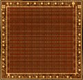
| + | <gallery> | ||
| + | Image:40010_am2_metal.jpg|40010 GA Metal Layer | ||
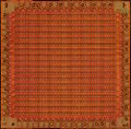
| + | Image:40010_am2_acid.jpg|40010 GA with Metal Layer removed | ||
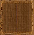
| + | Image:40226_am4_metal.jpg|40226 PreASIC Metal Layer | ||
| + | </gallery> | ||
| − | + | ==See also== | |
| − | + | *[[Gate Array and ASIC Pin-Outs]] | |
*[[Video modes]] : for other informations on colours and pixels. | *[[Video modes]] : for other informations on colours and pixels. | ||
| Line 848: | Line 452: | ||
*[[Synchronising with the CRTC and display]] : technical details on the relationship between Gate Array and CRTC. | *[[Synchronising with the CRTC and display]] : technical details on the relationship between Gate Array and CRTC. | ||
| − | [[Category:Hardware]][[Category:Programming]][[Category:Datasheet]][[Category:Graphic]][[Category:CPC Internal Components]] | + | [[Category:Hardware]][[Category:Programming]][[Category:Datasheet]][[Category:Graphic]][[Category:CPC Internal Components]][[Category:Electronic Component]] |
Revision as of 22:12, 3 March 2017
Gate Array
Also designated as Video gate Array (VGA, not to be confused with IBM PC compatible graphic card spec).
Contents
- 1 Introduction
- 2 What does it do?
- 3 Controlling the Gate Array
- 4 Register 0 - Palette Index (Pen selection)
- 5 Register 1 - Palette Data (Colour selection)
- 6 Register 2 - Select screen mode and ROM configuration
- 7 Register 3 - RAM Banking
- 8 Programming the Gate Array - Examples
- 9 Palette R,G,B definitions
- 10 Pictures
- 11 See also
Introduction
The gate array is a specially designed chip exclusively for use in the Amstrad CPC and was designed by Amstrad plc.
In the CPC+ system, the functions of the Gate-Array are integrated into a single ASIC. When the ASIC is "locked", the extra features are not available and the ASIC operates the same as the Gate-Array in the CPC allowing programs written for the CPC to work on the Plus without modification. The ASIC must be "un-locked" to access the new features.
In the KC Compact system, the functions of the Gate-Array are "emulated" in TTL chips, CIO, and its color translation EPROM.
In the "cost-down" version of the CPC6128, the functions of the Gate-Array are integrated into a ASIC.
The Gate Array is described here is the one found in a standard CPC.
What does it do?
The Gate Array is responsible for the display (colour palette, resolution, horizontal and vertical sync), interrupt generation and memory arrangement.
Controlling the Gate Array
The gate array is controlled by I/O. The gate array is selected when bit 15 of the I/O port address is set to "0" and bit 14 of the I/O port address is set to "1". The values of the other bits are ignored. However, to avoid conflict with other devices in the system, these bits should be set to "1".
The recommended I/O port address is &7Fxx.
The function to be performed is selected by writing data to the Gate-Array, bit 7 and 6 of the data define the function selected (see table below). It is not possible to read from the Gate-Array.
| Data Bit 7 | Data Bit 6 | Function |
| 0 | 0 | Select pen |
| 0 | 1 | Select colour for selected pen |
| 1 | 0 | Select screen mode, ROM configuration and interrupt control |
| 1 | 1 | RAM Memory Management (note 1) |
Note
This function is not available in the Gate-Array, but is performed by a device at the same I/O port address location. In the CPC464, CPC664 and KC compact, this function is performed in a memory-expansion (e.g. Dk'Tronics 64K RAM Expansion), if this expansion is not present then the function is not available. In the CPC6128, this function is performed by a PAL located on the main PCB, or a memory-expansion. In the 464+ and 6128+ this function is performed by the ASIC or a memory expansion. Please read the document on RAM management for more information.
Register 0 - Palette Index (Pen selection)
When bit 7 and bit 6 are set to "0", the remaining bits determine which pen is to have its colour changed. When bit 4 is set to "0", bits 3 to 0 define which pen is to be selected. When bit 4 is set to "1", the value contained in bits 3-0 is ignored and the border is selected.
The pen remains selected until another is chosen.
Each mode has a fixed number of pens. Mode 0 has 16 pens, mode 1 has 4 pens and mode 2 has 2 pens.
Summary
| Bit | Value | Function |
| 7 | 0 | Gate Array function "Pen Selection" |
| 6 | 0 | |
| 5 | - | not used |
| 4 | 1 | Select border |
| 3 | x | Ignored |
| 2 | x | |
| 1 | x | |
| 0 | x |
| Bit | Value | Function |
| 7 | 0 | Gate Array function "Pen Selection" |
| 6 | 0 | |
| 5 | - | not used |
| 4 | 0 | Select pen |
| 3 | x | Pen number |
| 2 | x | |
| 1 | x | |
| 0 | x |
Register 1 - Palette Data (Colour selection)
Once the pen has been selected its colour can then be changed. Bits 4 to 0 specify the hardware colour number from the hardware colour palette.
Even though there is provision for 32 colours, only 27 are possible. The remaining colours are duplicates of those already in the colour palette.
Summary
| Bit | Value | Function |
| 7 | 0 | Gate Array function "Colour selection" |
| 6 | 1 | |
| 5 | - | not used |
| 4 | x | Colour number x |
| 3 | x | |
| 2 | x | |
| 1 | x | |
| 0 | x |
Register 2 - Select screen mode and ROM configuration
This is a general purpose register responsible for the screen mode and the ROM configuration.
Screen mode selection
The function of bits 1 and 0 is to define the screen mode. The settings for bits 1 and 0 and the corresponding screen mode are given in the table below.
| Bit 1 | Bit 0 | Screen mode |
| 0 | 0 | Mode 0, 160x200 resolution, 16 colours |
| 0 | 1 | Mode 1, 320x200 resolution, 4 colours |
| 1 | 0 | Mode 2, 640x200 resolution, 2 colours |
| 1 | 1 | Mode 3, 160x200 resolution, 4 colours (undocumented) |
- Mode 3 is not official. From the combinations possible, we can see that 4 modes can be defined, although the Amstrad only has 3. Mode 3 is similar to mode 0, because it has the same resolution, but it is limited to only 4 colours. Mode 3 is not supported by the KC Compact (which outputs black in Mode 3).
Mode changing is synchronised with HSYNC. If the mode is changed, it will take effect from the next HSYNC.
ROM configuration selection
Bit 2 is used to enable or disable the lower ROM area. The lower ROM area occupies memory addresses &0000-&3fff and is used to access the operating system ROM. When the lower ROM area is is enabled, reading from &0000-&3FFF will return data in the ROM. When a value is written to &0000-&3FFF, it will be written to the RAM underneath the RAM. When it is disabled, data read from &0000-&3FFF will return the data in the RAM.
Similarly, bit 3 controls enabling or disabling of the upper ROM area. The upper ROM area occupies memory addressess &C000-&FFFF and is BASIC or any expansion ROMs which may be plugged into a ROM board/box. See the document on upper rom selection for more details. When the upper ROM area enabled, reading from &c000-&ffff, will return data in the ROM. When data is written to &c000-&FFFF, it will be written to the RAM at the same address as the ROM. When the upper ROM area is disabled, and data is read from &c000-&ffff it will be the data in the RAM.
Bit 4 controls the interrupt generation. It can be used to delay interrupts. See the document on interrupt generation for more information.
Summary
| Bit | Value | Function |
| 7 | 1 | Gate Array function |
| 6 | 0 | |
| 5 | - | not used |
| 4 | x | Interrupt generation control |
| 3 | x | 1=Upper ROM area disable, 0=Upper ROM area enable |
| 2 | x | 1=Lower ROM area disable, 0=Lower ROM area enable |
| 1 | x | Screen Mode slection |
| 0 | x |
Register 3 - RAM Banking
This register exists only in CPCs with 128K RAM (like the CPC 6128, or CPCs with Standard Memory Expansions). Note: In the CPC 6128, the register is a separate PAL that assists the Gate Array chip.
| Bit | Value | Function |
| 7 | 1 | Gate Array function 3 |
| 6 | 1 | |
| 5 | b | 64K bank number (0..7); always 0 on an unexpanded CPC6128, 0-7 on Standard Memory Expansions |
| 4 | b | |
| 3 | b | |
| 2 | x | RAM Config (0..7) |
| 1 | x | |
| 0 | x |
The 3bit RAM Config value is used to access the second 64K of the total 128K RAM that is built into the CPC 6128 or the additional 64K-512K of standard memory expansions. These contain up to eight 64K ram banks, which are selected with bit 3-5. A standard CPC 6128 only contains bank 0. Normally the register is set to 0, so that only the first 64K RAM are used (identical to the CPC 464 and 664 models). The register can be used to select between the following eight predefined configurations only:
 -Address-     0      1      2      3      4      5      6      7
 0000-3FFF   RAM_0  RAM_0  RAM_4  RAM_0  RAM_0  RAM_0  RAM_0  RAM_0
 4000-7FFF   RAM_1  RAM_1  RAM_5  RAM_3  RAM_4  RAM_5  RAM_6  RAM_7
 8000-BFFF   RAM_2  RAM_2  RAM_6  RAM_2  RAM_2  RAM_2  RAM_2  RAM_2
 C000-FFFF   RAM_3  RAM_7  RAM_7  RAM_7  RAM_3  RAM_3  RAM_3  RAM_3
The Video RAM is always located in the first 64K, VRAM is in no way affected by this register.
Programming the Gate Array - Examples
Defining the colours,
Setting pen 0 to Bright White.
LD BC,7F00 ;Gate Array port
LD A,%00000000+0 ;Pen number (and Gate Array function)
OUT (C),A ;Send pen number
LD A,%01000000+11 ;Pen colour (and Gate Array function)
OUT (C),A ;Send it
RET

Setting the mode and ROM configuration,
Mode 2, upper and lower ROM disabled.

LD BC,7F00 ;Gate array port
LD A,%10000000+%00001110 ;Mode and ROM selection (and Gate Array function)
OUT (C),A ;Send it
RET
Misc
The hardware colour number is different to the colour range used by the firmware, so a conversion chart is provided for the corresponding firmware/hardware colour values and the corresponding colour name.
Note
The firmware keeps track of the colours it is using. Every VSYNC (assuming interrupts are enabled) the firmware sets the colours. This enables the user to have flashing colours. If the user selects a new colour using the gate array, the new colour will flash temporarily and then return to its original colour. This is due to the firmware resetting the colour. When using the firmware, use its routines to select the colour, and the colour will remain.
Example: [For whatever reason, this example does NOT refer to the above firmware stuff]
ld bc,7f00+1 ;Gate array function (set pen)
;and pen number
out (c),c
ld bc,7f00 ;41
;Gate array function (set colour)
;and colour number
out (c),c
ret
Palette R,G,B definitions
There are 27 colours which are generated from red, green and blue mixed in different quantities. There are 3 levels of red, 3 levels of green and 3 levels of blue, and these can be thought of as off/no colour, half-on/half-colour, and on/full-colour.
To display a CPC image you will need to use a analogue monitor with a composite sync.
Palette sorted by Hardware Colour Numbers
| Hardware Number | Firmware Number | Colour Name | R % | G % | B % | Colour |
| 0 (40h) | 13 | White | 50 | 50 | 50 | |
| 1 (41h) | (13) | White | 50 | 50 | 50 | |
| 2 (42h) | 19 | Sea Green | 0 | 100 | 50 | |
| 3 (43h) | 25 | Pastel Yellow | 100 | 100 | 50 | |
| 4 (44h) | 1 | Blue | 0 | 0 | 50 | |
| 5 (45h) | 7 | Purple | 100 | 0 | 50 | |
| 6 (46h) | 10 | Cyan | 0 | 50 | 50 | |
| 7 (47h) | 16 | Pink | 100 | 50 | 50 | |
| 8 (48h) | (7) | Purple | 100 | 0 | 50 | |
| 9 (49h) | (25) | Pastel Yellow | 100 | 100 | 50 | |
| 10 (4Ah) | 24 | Bright Yellow | 100 | 100 | 0 | |
| 11 (4Bh) | 26 | Bright White | 100 | 100 | 100 | |
| 12 (4Ch) | 6 | Bright Red | 100 | 0 | 0 | |
| 13 (4Dh) | 8 | Bright Magenta | 100 | 0 | 100 | |
| 14 (4Eh) | 15 | Orange | 100 | 50 | 0 | |
| 15 (4Fh) | 17 | Pastel Magenta | 100 | 50 | 100 | |
| 16 (50h) | (1) | Blue | 0 | 0 | 50 | |
| 17 (51h) | (19) | Sea Green | 0 | 100 | 50 | |
| 18 (52h) | 18 | Bright Green | 0 | 100 | 0 | |
| 19 (53h) | 20 | Bright Cyan | 0 | 100 | 100 | |
| 20 (54h) | 0 | Black | 0 | 0 | 0 | |
| 21 (55h) | 2 | Bright Blue | 0 | 0 | 100 | |
| 22 (56h) | 9 | Green | 0 | 50 | 0 | |
| 23 (57h) | 11 | Sky Blue | 0 | 50 | 100 | |
| 24 (58h) | 4 | Magenta | 50 | 0 | 50 | |
| 25 (59h) | 22 | Pastel Green | 50 | 100 | 50 | |
| 26 (5Ah) | 21 | Lime | 50 | 100 | 0 | |
| 27 (5Bh) | 23 | Pastel Cyan | 50 | 100 | 100 | |
| 28 (5Ch) | 3 | Red | 50 | 0 | 0 | |
| 29 (5Dh) | 5 | Mauve | 50 | 0 | 100 | |
| 30 (5Eh) | 12 | Yellow | 50 | 50 | 0 | |
| 31 (5Fh) | 14 | Pastel Blue | 50 | 50 | 100 |
Palette sorted by Firmware Colour Numbers
| Firmware Number | Hardware Number | Colour Name | R % | G % | B % | Colour |
| 0 | 54h | Black | 0 | 0 | 0 | |
| 1 | 44h (or 50h) | Blue | 0 | 0 | 50 | |
| 2 | 55h | Bright Blue | 0 | 0 | 100 | |
| 3 | 5Ch | Red | 50 | 0 | 0 | |
| 4 | 58h | Magenta | 50 | 0 | 50 | |
| 5 | 5Dh | Mauve | 50 | 0 | 100 | |
| 6 | 4Ch | Bright Red | 100 | 0 | 0 | |
| 7 | 45h (or 48h) | Purple | 100 | 0 | 50 | |
| 8 | 4Dh | Bright Magenta | 100 | 0 | 100 | |
| 9 | 56h | Green | 0 | 50 | 0 | |
| 10 | 46h | Cyan | 0 | 50 | 50 | |
| 11 | 57h | Sky Blue | 0 | 50 | 100 | |
| 12 | 5Eh | Yellow | 50 | 50 | 0 | |
| 13 | 40h (or 41h) | White | 50 | 50 | 50 | |
| 14 | 5Fh | Pastel Blue | 50 | 50 | 100 | |
| 15 | 4Eh | Orange | 100 | 50 | 0 | |
| 16 | 47h | Pink | 100 | 50 | 50 | |
| 17 | 4Fh | Pastel Magenta | 100 | 50 | 100 | |
| 18 | 52h | Bright Green | 0 | 100 | 0 | |
| 19 | 42h (or 51h) | Sea Green | 0 | 100 | 50 | |
| 20 | 53h | Bright Cyan | 0 | 100 | 100 | |
| 21 | 5Ah | Lime | 50 | 100 | 0 | |
| 22 | 59h | Pastel Green | 50 | 100 | 50 | |
| 23 | 5Bh | Pastel Cyan | 50 | 100 | 100 | |
| 24 | 4Ah | Bright Yellow | 100 | 100 | 0 | |
| 25 | 43h (or 49h) | Pastel Yellow | 100 | 100 | 50 | |
| 26 | 4Bh | Bright White | 100 | 100 | 100 |
Intensities
The 0%, 50%, and 100% values in the above tables are "should-be" values. However, the real hardware doesn't exactly match that intensities. The actual intensities depend on the luminance mixing (R,G,B tied together via resistors), on chipset (classic CPC, or newer ASIC ones), and on the load applied by external hardware (Monitor, or TV set).
- CPC Palette - some more details
To calculate the colour value
Red
0% => do not add anything
50% => add 3
100% => add 6
Green
0% => do not add anything
50% => add 9
100% => add 18
Blue
0% => do not add anything
50% => add 1
100% => add 2
Green Screen Colours
On a green screen (where all colours are shades of green), the colours (in the software/firmware colours), are in order of increasing intensity. Black is very dark, and white is bright green, and colour 13 is a medium green. (Thanks to Mark Rison for this information)
Pictures
40010 GA Metal Layer
40010 GA with Metal Layer removed
40226 PreASIC Metal Layer


See also
- Video modes : for other informations on colours and pixels.
- Synchronising with the CRTC and display : technical details on the relationship between Gate Array and CRTC.