Difference between revisions of "Magic Sound Board"
From CPCWiki - THE Amstrad CPC encyclopedia!
(Created page with 'The MagicSound board is an expansion for the Aleste 520EX. == Pictures == <gallery> File:Magic-sound-PCB-rear-component-side.jpg|PCB rear/component File:Magic-sound-PCB-fro…') |
|||
| (19 intermediate revisions by one other user not shown) | |||
| Line 1: | Line 1: | ||
| − | The MagicSound board is | + | [[Category:Clones]][[Category:Music and sound]] |
| + | The MagicSound board from Patisonic is a 4-channel DMA sound expansion for the [[Aleste 520EX]] from the same company. | ||
| + | |||
| + | The '''Aleste 520EX''' is a rare CPC [[Clones|clone]] with 512Kbyte RAM, its [[Connector:Expansion port|expansion port]] includes some additional pins allowing external hardware to access the 512K RAM via DMA. The '''MagicSound''' board is probably even rarer, it's using the additional DMA pins on the expansion port, so it works only on the Aleste, not on normal CPCs. | ||
| + | |||
| + | == I/O Map and NMI Overview == | ||
| + | |||
| + | Port A10 A9 A8 A5 A3 A2 A1 A0 RW Expl. | ||
| + | FXDX 0 X X 0 X X X X The board selected. | ||
| + | F8DX 0 0 0 0 r r r r RW [[DMA Controller 8237]] | ||
| + | rrrr is reg number | ||
| + | D[7..0] Data | ||
| + | F9DX 0 0 1 0 (1) 0 r r -W TIMER [[8253 chip|8254]] CHANNELS 0,1,2 | ||
| + | rr is reg number | ||
| + | D[7..0] Data | ||
| + | F9DY 0 0 1 0 0 (1) r r -W TIMER [[8253 chip|8254]] CHANNELS 3, and DAC | ||
| + | nn is reg number | ||
| + | D[7..0] Data | ||
| + | FADX 0 1 0 0 X X c c -W VOLUME CONTROL | ||
| + | cc is channel number | ||
| + | D[5..0] Volume | ||
| + | FBDX 0 1 1 0 c c m m -W MAPPER | ||
| + | cc is channel number | ||
| + | mm is mapper's page register | ||
| + | D[5..0] inverted page number | ||
| + | After reset timers do not work until first write to it's regs | ||
| + | After dma end ('tc' signal) the [[NMI]] to Z80 generated | ||
== Pictures == | == Pictures == | ||
| − | <gallery> | + | <gallery caption="A Magic Sound board (with all components installed)"> |
| − | File:Magic-sound-PCB- | + | File:Magic-sound-PCB-front-solder-side.jpg|PCB front (solder side) |
| − | File:Magic-sound-PCB- | + | File:Magic-sound-PCB-rear-component-side.jpg|PCB rear (component side) |
File:Magic-sound-PCB-mounted.jpg|PCB mounted | File:Magic-sound-PCB-mounted.jpg|PCB mounted | ||
| − | |||
| − | |||
</gallery> | </gallery> | ||
| + | |||
| + | <gallery caption="Another Magic Sound board (non-functional: the 3.5mm socket, and a lot of chips aren't installed)"> | ||
| + | File:Deepfb-magic-sound-PCB-front-solder-side.jpg|PCB front (solder side) | ||
| + | File:Deepfb-magic-sound-PCB-rear-component-side.jpg|PCB rear (component side) | ||
| + | </gallery> | ||
| + | |||
| + | == Schematics == | ||
| + | |||
| + | <gallery> | ||
| + | File:Magic-sound-schematic1.gif|Schematic 1/2 (digital part) | ||
| + | File:Magic-sound-schematic2.gif|Schematic 2/2 (analog part) | ||
| + | </gallery> | ||
| + | |||
| + | == Magic Sound Chipset == | ||
| + | |||
| + | pcs russian western name description | ||
| + | 1 KR1810WT37 8237 D5 DMA controller | ||
| + | 2 KR1810WI54 8254 D3,D4 Programmable interval timer | ||
| + | 1 K1118PA1 MC10318 D21 8bit digital-analog-converter | ||
| + | 2 K555AP6 74LS245 D1,D2 8bit 3state transceiver | ||
| + | 1 K555ID4 74LS155 D14 2x2bit decoder/demult | ||
| + | 1 K555IR22 74LS373 D6 8bit 3state latch | ||
| + | 4 K555IR32 74LS170 D7,D8,D9,D10 4x4bit register file OC | ||
| + | 1 K555KP11 74LS257 D16 8-to-4 data selector | ||
| + | 2 K555LI1 74LS08 D18,D20 Quad AND gates | ||
| + | 1 K555LL1 74LS32 D19 Quad OR gates | ||
| + | 1 K555LN1 74LS04 D17 Hex inverters | ||
| + | 2 K555RU2 xxx D12,D11 16x4bit RAM with separate data in/out | ||
| + | 1 K555TR2 74LS279 D13 Quad Set-Reset Latches | ||
| + | 2 K555TM2 74LS74 D15,D25 Dual flipflop | ||
| + | 1 K561KP1 4052 D22 8-to-2 line analog multiplexer | ||
| + | 2 K561KT3 4066 D23,D24 Quad analog switches | ||
| + | |||
| + | In the schematics, all chips are on sheet1, except, D21..D24 on sheet2. | ||
Latest revision as of 21:52, 16 December 2010
The MagicSound board from Patisonic is a 4-channel DMA sound expansion for the Aleste 520EX from the same company.
The Aleste 520EX is a rare CPC clone with 512Kbyte RAM, its expansion port includes some additional pins allowing external hardware to access the 512K RAM via DMA. The MagicSound board is probably even rarer, it's using the additional DMA pins on the expansion port, so it works only on the Aleste, not on normal CPCs.
I/O Map and NMI Overview
 Port  A10 A9 A8 A5 A3 A2 A1 A0  RW Expl.
 FXDX    0  X  X  0  X  X  X  X     The board selected.
 F8DX    0  0  0  0  r  r  r  r  RW DMA Controller 8237
                                    rrrr is reg number
                                    D[7..0] Data
 F9DX    0  0  1  0 (1) 0  r  r  -W TIMER 8254 CHANNELS 0,1,2
                                    rr is reg number
                                    D[7..0] Data
 F9DY    0  0  1  0  0 (1) r  r  -W TIMER 8254 CHANNELS 3, and DAC
                                    nn is reg number
                                    D[7..0] Data
 FADX    0  1  0  0  X  X  c  c  -W VOLUME CONTROL
                                    cc is channel number
                                    D[5..0] Volume
 FBDX    0  1  1  0  c  c  m  m  -W MAPPER
                                    cc is channel number
                                    mm is mapper's page register
                                    D[5..0] inverted page number
 After reset timers do not work until first write to it's regs
 After dma end ('tc' signal) the NMI to Z80 generated
Pictures
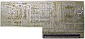
- A Magic Sound board (with all components installed)

PCB front (solder side)
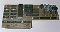
PCB rear (component side)

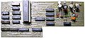
PCB mounted


- Another Magic Sound board (non-functional: the 3.5mm socket, and a lot of chips aren't installed)
PCB front (solder side)
PCB rear (component side)


Schematics

Schematic 1/2 (digital part)

Schematic 2/2 (analog part)


Magic Sound Chipset
 pcs russian      western  name          description
 1   KR1810WT37   8237     D5            DMA controller
 2   KR1810WI54   8254     D3,D4         Programmable interval timer
 1   K1118PA1     MC10318  D21           8bit digital-analog-converter
 2   K555AP6      74LS245  D1,D2         8bit 3state transceiver
 1   K555ID4      74LS155  D14           2x2bit decoder/demult
 1   K555IR22     74LS373  D6            8bit 3state latch
 4   K555IR32     74LS170  D7,D8,D9,D10  4x4bit register file OC
 1   K555KP11     74LS257  D16           8-to-4 data selector
 2   K555LI1      74LS08   D18,D20       Quad AND gates
 1   K555LL1      74LS32   D19           Quad OR gates
 1   K555LN1      74LS04   D17           Hex inverters
 2   K555RU2      xxx      D12,D11       16x4bit RAM with separate data in/out
 1   K555TR2      74LS279  D13           Quad Set-Reset Latches
 2   K555TM2      74LS74   D15,D25       Dual flipflop
 1   K561KP1      4052     D22           8-to-2 line analog multiplexer
 2   K561KT3      4066     D23,D24       Quad analog switches
In the schematics, all chips are on sheet1, except, D21..D24 on sheet2.