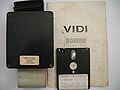
A video digitizer for the Amstrad CPC from Rombo Productions.
Technical
I/O Port Summary
 Port F8B0h - CRTC Index
 Port F8B1h - CRTC Data
 Port F9B0h - Config (W) and Capture Data (R)
 NMI - triggered on SYNC (on VSYNC, and maybe also on HSYNC?)
Config Bits
Configuration is done by writing to Port F9B0h:
0 Reset Brightness/Contrast to zero (0=No, 1=Reset)
1 Increment Contrast   (0=No, 1=Add +1)
2 Increment Brightness (0=No, 1=Add +1)
3 Enable NMI on Sync   (0=No, 1=Yes)
4-6 Transfer mode
     0=Stop Transfer
     1=Transfer SRAM to CPC
     3=Capture 320x200x4 to SRAM
     7=Capture 640x200x1 to SRAM
7 Not used by VIDI software (set to 0)
Note: additionally to above I/O controlled brightness/contrast, the hardware additionally has (externally accessible) brightness/contrast potentiometers for coarse adjustments, also the pots are REQUIRED for mode0 scans (where the brightness I/O ports are increasing from 0=min to 15=max during the 16-pass scan).
CRTC Registers
The digitizer contains a CRTC chip (the same CRTC chip that is also used in the CPC itself). The CRTC chip in the Vidi is used as address generator for writing to & reading from capture 16K SRAM. The CRTC registers are configured via Port F8B0h (index) and F8B1h (data). Usually set to following values:
crtc[00h] 75h or 50h ;horizontal total (-1)
crtc[01h] 50h        ;horizontal displayed
crtc[02h] 5Bh or ..  ;horizontal sync pos
crtc[03h] 11h        ;horizontal sync width
crtc[04h] 26h        ;vertical total (-1)
crtc[05h] 0          ;vertical total adjust
crtc[06h] 19h        ;vertical displayed
crtc[07h] 0          ;vertical sync pos
crtc[08h] 0          ;interlace mode
crtc[09h] 07h        ;max scanline (-1)
crtc[0Ah] 0          ;cursor start
crtc[0Bh] 0          ;cursor end
crtc[0Ch] 0          ;start addr high
crtc[0Dh] 0          ;start addr low
crtc[0Eh] 0          ;cursor high
crtc[0Fh] 0          ;cursor low
crtc[10h] N/A        ;lightpen high
crtc[11h] N/A        ;lightpen low
Most registers are set to fixed values. The vidi software modifies only two of them:
- CRTC[00h]. For AUX-to-SRAM it's set to 75h (vertical total=76h) (with capture writes being "paused" during hblank), for SRAM-to-CPU transfer it's set to 50h (vertical total=51h) (additional hblank cycles would be unneccesary overload for the software transfer; still there is one dummy-hblank cycle, probably required for the inner workings of the CRTC chip).
- CRTC[02h]. Set to 4Bh+xpos, used to adjust the horizontal position where scanning starts. Note: The vertical position can be also changed, but this is done by software delay between vsync and capture, not by CRTC registers.
In theory, more CRTC registers could be changed, for example, one could change the scanning region from 320x200 to 256x256. The Vidi software doesn't include any such features.
Note: Internally, the CRTC stores the scanline data in SRAM in the same "interleaved" format as it is also used in the CPC's VRAM (ie. line 0,8,16,24,etc.). However, this effect is "undone" when the CRTC reads the stored scanlines (so the CPU receives data without interleave. oe. line 0,1,3,4,etc.).
Scanning Modes
The software supports 3 modes (at hardware side, there are only 2 modes):
- Mode 2 - 640x200x1 - true hardware mode (0=black, 1=white)
- Mode 1 - 320x200x4 - true hardware mode (0=black, 1=dark grey, 2=white, 3=light grey)
- Mode 0 - 160x192x16 - special software mode: the software performs sixteen Mode 2 scans (with different brightness settings in each pass), and combines them to a 16-color image. Obviously, this method works only with still images (camcorder aimed at still image, or VCR with "freeze picture" mode). Moreover, the CPC with CTM640/CTM644 colour monitor can't display 16 grayscales so the picture will look like crap, however, it will look pretty much perfect on a GT64/GT65 green monitor. The software scans only 192 lines in this mode (not 200 lines), but this is just due to lazy programming (the programmer didn't handle the region "under" the OSD menu at the bottom of the screen). In mode 0 scanning, the user/software selected brightness is ignored (because the whole sixteen I/O selectable brightness values are used for the sixteen passes), so, brightness can be adjusted only via the potentiometer.
For the two hardware modes, the bits in the capture bytes are having the same format as CPC VRAM (observe that in Mode 1, white is color 2, not color 3). For the software mode, obviously, the format depends on the software (the VIDI software uses CPC VRAM format, with color 0..15 = black..white).
Disassembly
- Media:Vidi digitizer disassembly.txt - disassembled scanning functions from VIDI software
Pictures
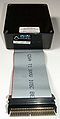
The VIDI video digitizer
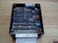
Intern VIDI
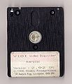
Vidi Disc

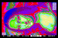
Example of VIDI digitizing

Example of VIDI digitizing

Example of VIDI digitizing

Mode 0 on GT65
Mode 0 on CTM644
VIDI video digitizer as seen on Ebay 2010


Publicity
- Vidi

Advert 1
Advert 2

Advert 3


Reviews
- ACU Issue 12, 1986, page 49, 50
- Amstradbladet 1987, Issue 4 page 8-11 (Danish)
- Amstrad Action, Issue 115, 1995 page 19
Manual
- VIDI Manual (pdf)
- VIDI Manual (txt)
Software Download
- Rombo Video Digitiser.zip (DSK for Emulators)
- Rombo Video Digitiser ROM (ROM for ROM expansions)
Software was available on cassette, disc, and (as an upgrade option) on ROM. The latter one requires an external ROM BOX to be of any use (the Vidi board doesn't include a ROM socket).
See also
- ARA Video Digitizer - another video digitizer (Jagot & Leon)