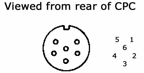
Amstrad CPC Monitor port pinout
| Pin No. | Signal Name | Description |
| 1 | R | Red analogue signal |
| 2 | G | Green analogue signal |
| 3 | B | Blue analogue signal |
| 4 | Sync | RGB switching control |
| 5 | GND | Common |
| 6 | LUM | Luminance |
This covers the CPC's RGB signal through the 6 pin DIN socket.
The + models use a 8 pin DIN that also includes stereo audio output,
and is not covered by this article.
