Difference between revisions of "Aleste 520EX"
(→Keyboard) |
|||
| Line 174: | Line 174: | ||
The Aleste has a JCUKEN keyboard, rather than a QWERTY keyboard. | The Aleste has a JCUKEN keyboard, rather than a QWERTY keyboard. | ||
* '''Unknown''' if this done by hardware, or by patched CPC bios (?) | * '''Unknown''' if this done by hardware, or by patched CPC bios (?) | ||
| − | * Normally, the key next to TAB '''should''' be Row8.Bit3 in the CPC matrix. And the BIOS should assign "Q" to it for QWERTY keyboards | + | * Normally, the key next to TAB '''should''' be Row8.Bit3 in the CPC matrix. And the BIOS should assign "Q" to it for english QWERTY keyboards, "A" for french "AZERTY" keyboards - or "J" for russian JCUKEN keyboards (though not sure if Patisonic has implemented it that way). |
_____ _____ _____ _____ _____ _____ _____ _____ _____ _____ | _____ _____ _____ _____ _____ _____ _____ _____ _____ _____ | ||
Revision as of 19:09, 3 February 2010

The Aleste 520EX is a clone of the Amstrad CPC 6128 developed 1993 Patisonic in Omsk (Siberia). The Aleste is rare, according to Patisonic themselves, they "produced several dozens of the model, some of them was in 'kit' form".
Additionally to the standard CPC6128 features, it includes a number of extra features: 64-color palette, double color depth (eg. 16 color at high 320x200 resolution), battery-backed Real Time Clock chip, 512Kbyte RAM (of which 192K can be accessed as on 64K CPC with 128K dk'tronics memory expansion), 8bit printer port, expanded keyboard matrix with 10 additional keys, two software controlled LEDs, extended Expansion Port (with additional pins for DMA support).
The computer works with Amstrad CP/M and MSXDOS as well (note: MSXDOS is a CP/M clone, which uses a FAT filesystem, as used on MSX and MS-DOS computers, instead of the normal CP/M filesystem).
Contents
Amstrad Mode
Differences:
- Interrupts can't be manually cleared. This was possible on the CPC by writing to the Gate Array with data bit 7 set 1, bit 6 set to 0 and bit 4 set to 1. In the Aleste this bit is controls an LED.
- Decoding of it's equivalent of the Gate-Array is based on A15 only.
- The Aleste uses a patched CPC6128 Operating System ROM. It is patched to use the Aleste's 8-bit printer port and has a different startup message.
Special Mode
At this mode computer have different memory manager. The manager seems same like MSX mapper and could swicth ON any 16KB page of whole memroy at the any of 16KB page of CPU memory.
The mode have different color coding system. It has the color lookup table (CLUT) or another name pallette. That is dual port memory one prot for coversion pixel's color number to RGB levels. But second for CPU acccess. There is 2 bits for each channel at the pallette present, then it lets to have 64 colors.
The mode have two additional modes with 32KB of video memory. Pixel encoding the same as at Amstrad mode but each line has twice more bytes (and pixels). Two 16KB pages transfer to output, one buffer for odd and second even lines of screen.
The computer have also mc146818 compatible RTC and a 8251 compatible serial. A serial mouse can be used.
The 8253 timer is used to generate transmit and receive clock for serial. In addition the CURSOR output of the CRTC is connected as a trigger which is then connected to the colour hardware. So the CRTC cursor can be used to switch colours by the hardware.
Aleste ROM is 64KB, additional page have BIOS SETUP and MSXDOS Boot Loader.
The BIOS SETUP lets control over: date and time, boot drive, RAM disk, screen mode and style, printer, serial port, and mouse.
At the boot time computer loads BIOS and MSXBDOS (BIOS for Disc BIOS) from a bood disc. After that COMMAND.COM (MSXDOS). Computer can bott from RAM disc as well. Computer go to AMSTRAD mode when "Shift" is pressed while reset.
Magic Sound Expansion Board
Additional sound board MagicSound is a four channel DMA playback. Supports 8 bit per sample, 6 bits of volume per channel, and 16bit samplerate timer per channel. Computer uses the board for playing STM (Scream Tracker) files.
VDP Emulator (is this an expansion board?)
Computer have "GameBios" with is emulator of VDP9938. it was sufficiently - to replace the first several kilos-byte of game and MSX2 game worked. Certainly, video processor MSX is by apparatus sharpened for the games, but they worked sufficiently rapidly to 8MGts of game on "alesta" in order in them to play. Game "FireBird" typical "vertical scroller" worked very well.
Foton Expansion Board
Another additional board FOTON is a "Light Processor". The board have D54 interface and Aleste with special FX application controls over club's light.
Pictures
- Pictures from http://aleste520.narod.ru
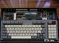
PCB and Keyboard
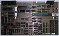
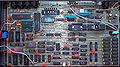
PCB top (component side)
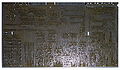
PCB bottom (solder side)
PCB illustrated


The above photos are showing a more or less fully assembled Aleste (the LEDs are missing, and, more important, there is no connection for an internal or external power supply attached to the mainboard - unless the owner used the Expansion Port connector to inject power supply voltages).
- Pictures from http://www.zonadepruebas.com
PCB and Keyboard
PCB only

Rear-connectors
Bottom


This version has 7pin+7pin sockets for printer (normal would be 5pin+7pin, though the extra pins are most probably left unused).
Schematics
Schematic 1/4
Schematic 2/4
Schematic 3/4
Schematic 4/4
Component Map


Documents
- Media:Aleste-Programming-Manual-English.txt - original programming manual (english version, ported to ASCII format)
Technical
| I/O | Decoded as | Port | Read | Write |
| #7CXX | %0xxxxx00 xxxxxxxx | Mapper page 0 (note 1)] | Read | Write |
| #7DXX | %0xxxxx01 xxxxxxxx | Mapper page 1 (note 1) | Read | Write |
| #7EXX | %0xxxxx10 xxxxxxxx | Mapper page 2 (note 1) | Read | Write |
| #7FXX | %0xxxxx11 xxxxxxxx | Mapper page 3 (note 1) | Read | Write |
| #7CXX | %0xxxxxxx xxxxxxxx | Multiport (note 3)] | - | Write |
| #BCXX | %x0xxxx00 xxxxxxxx | 6845 CRTC Index | - | Write |
| #BDXX | %x0xxxx01 xxxxxxxx | 6845 CRTC Data Out | - | Write |
| #BEXX | %x0xxxx10 xxxxxxxx | 6845 CRTC Status (as far as supported) | Read | - |
| #BFXX | %x0xxxx11 xxxxxxxx | 6845 CRTC Data In (as far as supported) | Read | - |
| #DFXX | %xx0xxxxx xxxxxxxx | Upper ROM Bank Number (note 9) | - | Write |
| #F4XX | %xxxx0x00 xxxxxxxx | 8255 PIO Port A (PSG/8253 Timer/Real-Time Clock data) | Read | Write |
| #F5XX | %xxxx0x01 xxxxxxxx | 8255 PIO Port B (Vsync,PrnBusy,Tape,etc.) | Read | - |
| #F6XX | %xxxx0x10 xxxxxxxx | 8255 PIO Port C (KeybRow, Real-Time-Clock control,,Tape,PSG Control) | - | Write |
| #F7XX | %xxxx0x11 xxxxxxxx | 8255 PIO Control-Register | - | Write |
| #FA7E | %xxxxx0x0 0xxxxxxx | Floppy Motor Control (for 765 FDC) | - | Write |
| #FABF | %xxxxx0x0 1xxxxxxx | EXTPORT (note 10) | - | Write |
| #FB7E | %xxxxx0x1 0xxxxxx0 | 765 FDC (internal) Status Register | Read | - |
| #FB7F | %xxxxx0x1 0xxxxxx1 | 765 FDC (internal) Data Register | Read | Write |
1.Mapper bits 7 and 6 of the data must be 1 for the Mapper write.
2.Printer data-bits are connected to AY I/O port B.
3. Multiport is similar to the Gate-Array in cpc.
| bit 7 | bit 6 | Action |
| 0 | 0 | Pen index write (note 5) |
| 0 | 1 | Pen ink write (note 6) |
| 1 | 0 | Mode, Rom enable, Leds (note 7) |
| 1 | 1 | Used by mapper |
5. If bit 3 is set, border is selected. Otherwise bits 3..0 define the pen index.
6. The number is converted by IC D62. When MAPPER is set in EXTPORT, then the numbers effectively define R,G,B with 2 bits per element, but the rom then changes the order of the bits before it gets to the hardware. When MAPPER is not set, the number is equivalent to the CPC's Gate-Array colour value, but this is looked up in IC D62 and converted into a 2-bit per element R,G,B for the aleste video hardware.
7. bit 0,1 define the mode. The actual resolution is then dependant on bit 1 of EXTPORT.
8. bit 2 is the enable/disable for the lower rom. bit 3 is the enable/disable for the upper rom. bit 4 defines the RUS led. bit 5 defines the CAPS led.
9. The number is looked up in IC and converted into another number which is the 16K page index in the Aleste's internal 64k ROM.
10. bit 2 = enable/disable MAPMOD (changes how colour is decoded and how mapper values are decoded), bit 3 = force video to black, bit 4 = Enable 8253 timer. Any I/O write then accesses 8253 with data comming from 8255 port A. Bit A0/A1 of I/O port defines 8253 register, bit 5 = if 0, then AY is accessed when read/write to 8255 port A, if 1 then real-time clock is accessed with read/write to 8255 port A. When real-time clock is selected, bits 3..0 of PPI port C are used to define real-time clock operation. DS bit 2, AS bit 1, R/W bit 0. So combinations are 2, write address, 4 write data, 5 read data.
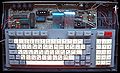
Keyboard
The Aleste uses a MSX keyboard, as seen by the characteristic five function keys. The mainboard contains some excessive TTL logic, assisted by the upper data bits of the VDKEY eprom, that translates the MSX matrix to a CPC matrix.
So, at I/O port level, the CPU "sees" a CPC matrix, not a MSX matrix. When running MSXDOS, this leads to the funny situation that MSXDOS must undo the hardware MSX-to-CPC translation by some software CPC-to-MSX translation.
The keyboard has some additional keys, which aren't on normal CPC keyboards:
- F1/F6, F2/F7, F3/F8, F4/F9, F5/F10 - MSX-style function keys, mapped to keyboard row 10, bits 7,6,5,4,3.
- HELP, INS, b - additional keys, mapped to keyboard row 10, bits 2,1,0.
- R/L - Russian/Latin mode, mapped to keyboard row 9, bit6 (aka joystick Fire3).
- RES - Reset button, goes to /RESET signal.
- Four unknown keys - These keys (above the numeric keypad) may be unused, or having same function as other keys?
The Aleste has a JCUKEN keyboard, rather than a QWERTY keyboard.
- Unknown if this done by hardware, or by patched CPC bios (?)
- Normally, the key next to TAB should be Row8.Bit3 in the CPC matrix. And the BIOS should assign "Q" to it for english QWERTY keyboards, "A" for french "AZERTY" keyboards - or "J" for russian JCUKEN keyboards (though not sure if Patisonic has implemented it that way).
 _____ _____ _____ _____ _____                 _____ _____ _____   _____ _____
|F1/6 |F2/7 |F3/8 |F4/9 |F5/10|               |HELP |INS  | DEL | |N/A  | RES |
|_____|_____|_____|_____|_____|               |_____|_____|_____| |_____|_____|
 _____ ___ ___ ___ ___ ___ ___ ___ ___ ___ ___ ___ ___ ___ _____   ___ ___ ___
| ESC | ; | 1 | 2 | 3 | 4 | 5 | 6 | 7 | 8 | 9 | 0 | _ | b |  BS | |N/A|N/A|N/A|
|_____|___|___|___|___|___|___|___|___|___|___|___|___|___|_____| |___|___|___|
|  TAB  | J | C | U | K | E | N | G | { | } | Z | H | : | / |   | | F7| F8| F9|
|_______|___|___|___|___|___|___|___|___|___|___|___|___|___|   | |___|___|___|
|  CTRL  | F | Y | W | A | P | R | O | L | D | V | \ | . |RETURN| | F4| F5| F6|
|________|___|___|___|___|___|___|___|___|___|___|___|___|______| |___|___|___|
|CAPS| R/L | Q | | | S | M | I | T | X | B | @ | '  |   | U |   | | F1| F2| F3|
|____|_____|___|___|___|___|___|___|___|___|___|____| L |___| R | |___|___|___|
|  SHIFT | COPY|         SPACE              | SHIFT |   | D |   | | F0| F.|ENT|
|________|_____|____________________________|_______|___|___|___| |___|___|___|
Technical specs
- CPU: Z80
- Clock: 4Mhz (CPC mode derived from a 16Mhz crystal), 3.2Mhz (Aleste mode derived from a 13Mhz crystal)
- Memory manager: Dk'Tronics compatible memory mapper (CPC mode), msx-mapper (Aleste mode)
- Memory: 512КБ (up to 2МБ)
- Audio: AY8910
- Graphics:
- 256x212:16 colors
- 512x212:4 colors
- 320x200:16 colirs
- 640x200:4 colors
- 640x400:4 colors interleaved
- Palette 64 colors
- Hardware scroll (standard CRTC hardware scroll)
- Floppy disk 3.5"
- Mouse
- RTC (mc146818 compatible)
- Expansion slot
- 19 address lines
- DMA to whole memory
- External board MagicSound
- 4 channels
- 8 bits per channel
- Stereo output
- Touch screen (only prototype)
- Light-Processor with D54
Software
- MSXDOS
- С compiler
- GUI Debugger
- GameBIOS with VDP emulator
- Text editor PowerEdit
- Text files converter TRC. Convert between MSX, Aleste, and DOS
- Disk Fixer (ported)
- Disk Edit (ported)
- Image viewer
- Player of S3M, STM files
- Editor of S3M, STM files
- Games ported from MSX2
- VampireKiller
- KingValery 2
- FireBird
- MetalGear
Aleste Chipset
Note: The part numbers printed on the chips may look like "KPxxx" (cyrillic) instead of "KRxxx" (latin).
Main Chipset
pcs russian    western  description    location
 1  Z80A CPU   Z80A     CPU            (D30=sheet2)
 1  UM6845     6845     CRTC           (D25=sheet2)
 1  AY-3-8910  AY3-8910 PSG, Dual I/O  (D18=sheet2) (with TWO I/O ports, unlike as in CPC)
 4  KR1802IR1  AM29705  RAM 2x16x4     (D60,D61=sheet2=palette, D62,D63=sheet4=keyboard)
 1  KR1810WG72 uPD765   FDC            (D70=sheet3)
 1  KR580WI53  8253     baudrate timer (D33=sheet4) (/CS=/CS53, A0,A1=A0,A1, D0-D7=AY0-AY7=PPIpa) (/WR only, no /RD) (CLK0,CLK1=WGPTCLK=16MHz/n, see sheet3)
 1  KR580WW51A 8251(A?) usart/mouse    (D34=sheet2) (A12=/CS, A8=C/D)
 1  KR580WW55A 8255     PPI            (D17=sheet2)
 1  KR512WI1   MC146818 RTC            (D19=sheet2)
 16 K565RU7K   HM50256  DRAM 256Kx1    (D1..D16=sheet3) (512Kbyte)
 1  K573RF4    27512    EPROM 64Kx8    (D31=sheet2) (BIOS/BASIC/BOOT/AMSDOS)
 2  K573RF2    2764     EPROM 2Kx8     (D62=COLDAT=sheet1, D65=VDKEY=sheet1)
 1  K155RE3    27S18    PROM 32x8 OC   (D69="Af"=sheet3=floppy) (dummy FP0..FP3, disk /GATE, to D72 count --> DW --> FDC)
 2  (KR)556RT4 27S20    PROM 256x4 OC  (D28="M"=MAP14..MAP17=sheet2, D67="R"=ROMEN/RAMEN etc.=sheet1)
Further Chips
pcs russian    western  description    location
 1  K170AP2    SN75150  rs232 dual line driver   (D86=sheet4)
 1  K555AP6    74LS245  8bit 3state tranceiver   (D89=sheet3)
 2  K555ID4    74LS155  2x2bit decoder/demult    (D54=sheet1, D74=sheet3)
 1  K555ID10   74LS145  bcd demultiplexer        (D80=sheet4)
 1  K555IE5    74LS93   4bit (1bit+3bit) counter (D72=sheet3)
 1  K555IE10   74LS161  4bit counter             (D37=sheet1)
 4  K555IR11A  74LS194  4bit shift register      (D39,D49=sheet1, D50,D51=sheet2)
 4  K555IR22   74LS373  8bit 3state latch        (D45,D46,D47,D48=sheet1) (RAM 16bit-to-8bit cpu/vram bus)
 2  K555IR23   74LS374  8bit 3state flipflop     (D58=sheet3, D84=sheet4)
 2  K555IR32   74LS170  4x4bit register file OC  (D87,D88=sheet2)
 6  K555KP2    74LS153  2x 4vstup. multiplexer   (D20,D21,D22,D23,D52,D53=sheet2)
 2  K555KP7    74LS151  8bit multiplexer         (D24=sheet2,D81=sheet4)
 1  K555KP11   74LS257  8-to-4 data selector     (D38=sheet1) (clock select)
 1  K555KP12   74LS253  2x 4vstup. multiplexer, TS "8-to-2 line 3-state noninverting data selector/multiplexer" (D26=sheet3)
 .. K555LA3    74LS00   Quad NAND gates          (various)
 .. K555LE1    74LS02   Quad NOR gates           (various)
 .. K555LI1    74LS08   Quad AND gates           (various)
 .. K555LL1    74LS32   Quad OR gates            (various)
 .. K555LN1    74LS04   Hex inverters            (various)
 1  K555LN2    74LS05   Hex inverters, OC        (D76=sheet3)
 5  K555TM2    74LS74   Dual flipflop            (D40,D77,D66,D57=sheet1, D71=sheet3)
 6  K555TM9    74LS174  6bit flipflop            (D32,D55,D56=sheet1, D59=sheet2, D68=sheet3, D79=sheet4)
 1  K561IE10   MC14520B dual up binary counter   (D63,D64=sheet1)
Weblinks
- http://aleste520.narod.ru - site dedicated to aleste (mainly english, plus some russian docs)