Difference between revisions of "Aleste 520EX"
(→Documents) |
(→Documents) |
||
| Line 38: | Line 38: | ||
* [[Media:Aleste-Programming-Manual-English.txt]] - original programming manual (english version, ported to ASCII format) | * [[Media:Aleste-Programming-Manual-English.txt]] - original programming manual (english version, ported to ASCII format) | ||
* [[Aleste Translation PROMs and EPROMs]] - description of the numbers in the look-up PROMs/EPROMs | * [[Aleste Translation PROMs and EPROMs]] - description of the numbers in the look-up PROMs/EPROMs | ||
| − | * [[Media:Aleste Interview Deepfb Valeriy.h t m l]] - Interview with of the Aleste developers (to view the file: repair the extension, and/or | + | * [[Media:Aleste Interview Deepfb Valeriy.h t m l]] - Interview with one of the Aleste developers (to view the file: repair the extension, and/or insert HTML and /HTML tags - for some reason, cpcwiki doesn't support the html format) |
== Weblinks == | == Weblinks == | ||
Revision as of 07:28, 21 February 2010

The Aleste 520EX is a clone of the Amstrad CPC 6128 developed 1993 by Patisonic in Omsk (Siberia). The Aleste is rare, according to Patisonic themselves, they "produced several dozens of the model, some of them was in 'kit' form".
Additionally to the standard CPC6128 features, it includes a number of extra features: 64-color palette, double color depth in slightly decreased horizontal resolution mode (eg. 16 color at 256x200 resolution), battery-backed Real Time Clock chip, 512Kbyte RAM (of which 192K can be accessed as on 64K CPC with 128K dk'tronics memory expansion), 8bit printer port, expanded keyboard matrix with 10 additional keys, two software controlled LEDs, extended Expansion Port (with additional pins for DMA support).
Contents
Technical
- Aleste 520EX - I/O Ports - I/O Ports, Memory, etc.
- Aleste 520EX - Schematics - Schematics, Chipset, etc.
- Aleste 520EX - Expansions - Hardware Expansions, External Connectors, etc.
- Aleste 520EX - Software - CPC software, CP/M, MSXDOS, and games ported to Aleste
- Aleste 520EX - Misc - Unsorted Notes
Pictures
- Pictures from http://aleste520.narod.ru
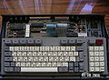
PCB and Keyboard
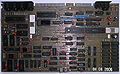
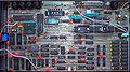
PCB top (component side)
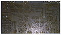
PCB bottom (solder side)
PCB illustrated


The above photos are showing a more or less fully assembled Aleste (the LEDs are missing, and, more important, there is no connection for an internal or external power supply attached to the mainboard - unless the owner used the Expansion Port connector to inject power supply voltages).
- Pictures from http://www.zonadepruebas.com
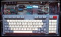
PCB and Keyboard
PCB only

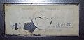
Rear-connectors
Bottom


This version has 7pin+7pin sockets for printer (normal would be 5pin+7pin, though the extra pins are most probably left unused).
Documents
- Media:Aleste-Programming-Manual-English.txt - original programming manual (english version, ported to ASCII format)
- Aleste Translation PROMs and EPROMs - description of the numbers in the look-up PROMs/EPROMs
- Media:Aleste Interview Deepfb Valeriy.h t m l - Interview with one of the Aleste developers (to view the file: repair the extension, and/or insert HTML and /HTML tags - for some reason, cpcwiki doesn't support the html format)
Weblinks
- http://aleste520.narod.ru - site dedicated to aleste (mainly english, plus some russian docs)