Difference between revisions of "Dk'tronics Real Time Clock"
(→Downloads) |
|||
| (11 intermediate revisions by the same user not shown) | |||
| Line 3: | Line 3: | ||
Contains following components: HD146818P ([[PC compatible RTC chip|PC-style RTC]]), a TMP[[Z80 PIO|Z84C20]]P ([[Z80 PIO]]), 74LS00 (Quad NAND), 74LS138 (demux), 74LS175 (4bit latch), 9pin male DSUB connector (used as an 8bit general-purpose I/O port), and a rechargeable 3.6V battery. | Contains following components: HD146818P ([[PC compatible RTC chip|PC-style RTC]]), a TMP[[Z80 PIO|Z84C20]]P ([[Z80 PIO]]), 74LS00 (Quad NAND), 74LS138 (demux), 74LS175 (4bit latch), 9pin male DSUB connector (used as an 8bit general-purpose I/O port), and a rechargeable 3.6V battery. | ||
| + | The battery is charged while the computer is switched on. The data will be retained for several months even if the computer is not used during this time. | ||
| + | |||
| + | Uses a Z80 PIO chip to control the HD146818 RTC chip via port A. Do not use Port A as this will affect the RTC operation. | ||
FBE0h Dk'tronics Real Time Clock - [[Z80 PIO]] Port A Data ([[PC compatible RTC chip|HD146818P]] RTC Data bus) | FBE0h Dk'tronics Real Time Clock - [[Z80 PIO]] Port A Data ([[PC compatible RTC chip|HD146818P]] RTC Data bus) | ||
| − | FBE1h Dk'tronics Real Time Clock - [[Z80 PIO]] Port B Data (General Purpose 8bit I/O Port) | + | FBE1h Dk'tronics Real Time Clock - [[Z80 PIO]] Port B Data, used for external control (General Purpose 8bit I/O Port) |
FBE2h Dk'tronics Real Time Clock - [[Z80 PIO]] Port A Control | FBE2h Dk'tronics Real Time Clock - [[Z80 PIO]] Port A Control | ||
FBE3h Dk'tronics Real Time Clock - [[Z80 PIO]] Port B Control | FBE3h Dk'tronics Real Time Clock - [[Z80 PIO]] Port B Control | ||
| − | FBE8h Dk'tronics Real Time Clock - | + | FBE8h Dk'tronics Real Time Clock - Control port for RTC chip (4bit latch) '''(details unknown)''' |
| − | + | Port B is connected directly to a standard 9-way connector on the left of the interface. | |
| − | + | ||
== Software == | == Software == | ||
| Line 76: | Line 78: | ||
== Reviews == | == Reviews == | ||
| − | + | Reviewed in [[Amstrad Computer User]], July 1987, pages 28 and 29. | |
| − | + | <gallery> | |
| + | Amstrad Computer User8707 028.jpg | ||
| + | Amstrad Computer User8707 029.jpg | ||
| + | </gallery> | ||
== Manuals == | == Manuals == | ||
| + | * [[Media:HD146818 datasheet.pdf|Hitachi HD146818 datasheet]] | ||
* [[Media:Dktronics RTC Manual English.pdf|Dk'tronics RTC Manual (English)]] | * [[Media:Dktronics RTC Manual English.pdf|Dk'tronics RTC Manual (English)]] | ||
* [[Media:Dktronics RTC Manual German.pdf|Dk'tronics RTC Manual (German)]] | * [[Media:Dktronics RTC Manual German.pdf|Dk'tronics RTC Manual (German)]] | ||
| Line 88: | Line 94: | ||
* [[File:DktronicsRtcDriver.zip]] - none such? | * [[File:DktronicsRtcDriver.zip]] - none such? | ||
| − | + | [[Category:Peripherals]] | |
| + | [[Category:Hardware]] | ||
Latest revision as of 10:42, 3 April 2025
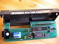
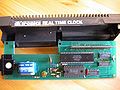
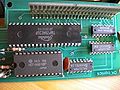
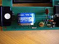
Technical
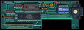
Contains following components: HD146818P (PC-style RTC), a TMPZ84C20P (Z80 PIO), 74LS00 (Quad NAND), 74LS138 (demux), 74LS175 (4bit latch), 9pin male DSUB connector (used as an 8bit general-purpose I/O port), and a rechargeable 3.6V battery.
The battery is charged while the computer is switched on. The data will be retained for several months even if the computer is not used during this time.
 Uses a Z80 PIO chip to control the HD146818 RTC chip via port A. Do not use Port A as this will affect the RTC operation.
 FBE0h  Dk'tronics Real Time Clock - Z80 PIO Port A Data (HD146818P RTC Data bus)
 FBE1h  Dk'tronics Real Time Clock - Z80 PIO Port B Data, used for external control (General Purpose 8bit I/O Port)
 FBE2h  Dk'tronics Real Time Clock - Z80 PIO Port A Control
 FBE3h  Dk'tronics Real Time Clock - Z80 PIO Port B Control
 FBE8h  Dk'tronics Real Time Clock - Control port for RTC chip (4bit latch) (details unknown)
 Port B is connected directly to a standard 9-way connector on the left of the interface.
Software
Included BASIC and CP/M+ drivers:
- RSX.BAS (loader) and RSX.BIN (binary)- allows to change the time under BASIC, using following RSX commands
- |SETTIME,yy%,mm%,dd%,dayofweek%,hour%,min%,sec%
- |ASKTIME,@yy%,@mm%,@dd%,@dayofweek%,@hour%,@min%,@sec%
- |POKERTC,index%,value%
- |PEEKRTC,index%,@value%
- |TIMEON,xpos%,ypos%,interval%
- |TIMEOFF
- |ALARMON,hour%,min%,sec%,flag%
- |ALARMOFF
- CLOCK.COM - installs the clock under CP/M+
- Thereafter, it should be accessible with standard DATE command, and, it should add timestamps to files).
- According to english manual, time is set by "CLOCK dd/mm/yy hh/mm/ss" rather than by using the DATE command (?)
- Unknown how the timestamps are stored on disk? The normal AMSDOS filesystem / directory entries don't include timestamps.
- According german manual, something is (the startup message?) "Datomat RTC und Cdos sind Warenzeichen von CMS International" (=Datomat RTC and Cdos are trademarks of CMS International)
Timestamps
Below method uses Directory Entries with User Number 31 for Timestamps. Which should be incompatible with AMSDOS, so it is probably NOT used in the CPC. On the CPC, the timestamps <might> be maybe stored in the bootstrap sectors...?
Time stamps - P2DOS and CP/M Plus support time stamps, which are stored in each fourth directory entry.
This entry contains the time stamps for the extents using the previous three directory entries. Note that you really have time stamps for each extent, no matter if it is the first extent of a file or not. The structure of time stamp entries is:
 1 byte status 0x21
 8 bytes time stamp for third-last directory entry
 2 bytes unused
 8 bytes time stamp for second-last directory entry
 2 bytes unused
 8 bytes time stamp for last directory entry
A time stamp consists of two dates: Creation and modification date (the latter being recorded when the file is closed). CP/M Plus further allows optionally to record the access instead of creation date as first time stamp.
 2 bytes (little-endian) days starting with 1 at 01-01-1978
 1 byte hour in BCD format
 1 byte minute in BCD format
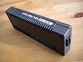
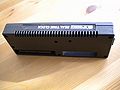
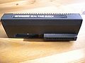
Photos
- dk'tronics Real Time Clock - 464/664 version
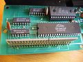
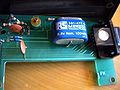
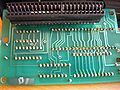
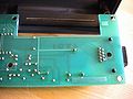
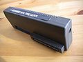


- dk'tronics Real Time Clock 300dpi scans by Robcfg - 6128 version
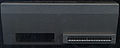
Front
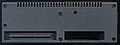
Back
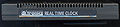
Top
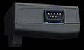
Side
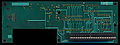
PCB Top
PCB Bottom

Reviews
Reviewed in Amstrad Computer User, July 1987, pages 28 and 29.


Manuals
Downloads
- File:DktronicsRtcDriver.zip - none such?