Difference between revisions of "DIY Cartridge"
From CPCWiki - THE Amstrad CPC encyclopedia!
| Line 1: | Line 1: | ||
| − | [[Image:DIY_Cart_1.png| | + | [[Image:DIY_Cart_1.png|420px|right]] |
| + | |||
| + | [[Image:DIY_Cart_6.png|420px|right]] | ||
=== Description === | === Description === | ||
| Line 13: | Line 15: | ||
- All vias are done at component pins to reduce drilling and soldering | - All vias are done at component pins to reduce drilling and soldering | ||
| + | |||
| + | === Building the Cartridge === | ||
The PCB dimensions are identical to an original cartridge and will fit in the original housing. The PCB used should be 1.5mm thick with double-sided 35µm copper. | The PCB dimensions are identical to an original cartridge and will fit in the original housing. The PCB used should be 1.5mm thick with double-sided 35µm copper. | ||
| − | Components should be mounted on the side with the ground plain. | + | Components should be mounted on the side with the ground plain. The capacitor is 100nf. |
The Layout file is as always mirror imaged. | The Layout file is as always mirror imaged. | ||
| − | |||
Revision as of 13:52, 10 December 2010
Description
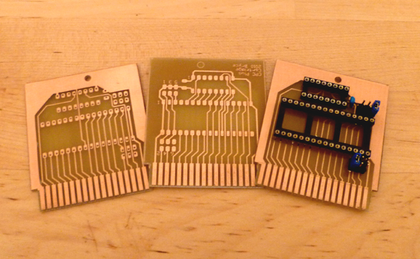
The file below is the PCB Layout for a standard plus cartridge with
a few minor changes:
- No LKs are bridged by default
- LKs use standard PCB jumpers for quick swapping
- All vias are done at component pins to reduce drilling and soldering
Building the Cartridge
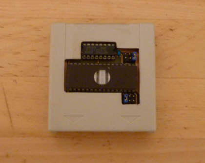
The PCB dimensions are identical to an original cartridge and will fit in the original housing. The PCB used should be 1.5mm thick with double-sided 35µm copper.
Components should be mounted on the side with the ground plain. The capacitor is 100nf.
The Layout file is as always mirror imaged.
File:Cartridge Layout.pdf - PCB Track Layout
Bryce.

