Difference between revisions of "Joystick Y-cables"
| (30 intermediate revisions by 7 users not shown) | |||
| Line 1: | Line 1: | ||
| − | [[Image: | + | [[Image:Joy-Y.jpg|thumb|Joystick Y-cable]] |
| − | + | ||
| − | + | Y-cables for [[Digital Joysticks]] were made by 3rd party vendors as a replacement to the original [[Amstrad JY-1/JY-2 joysticks|JY-2 joystick]] for the Amstrad CPC computers. | |
| − | In order to push sales of Amstrad's own joysticks, Amstrad designed the CPC with one joystick port only which had two | + | In order to push sales of Amstrad's own joysticks, Amstrad designed the CPC with one joystick port only which had two common signal pins. The idea was to sell one joystick which forwarded the second common signal to a built-in joystick port, to which the second joystick could be connected. |
As the quality of the Amstrad joysticks was lousy, using an Y-cable together with other joysticks was the preferred solution. | As the quality of the Amstrad joysticks was lousy, using an Y-cable together with other joysticks was the preferred solution. | ||
| − | == | + | == Technical == |
| − | == | + | Basically, Pin8 needs to be swapped with Pin9 for the second joystick. However, the cable should also contain '''diodes''' in order to prevent conflicts between the two joysticks. |
| + | |||
| + | For example, if Player 1 moves UP-'''and'''-RIGHT then UP and RIGHT are shortcut with each other. In result, without the diodes, Player 2 would automatically move UP-'''and'''-RIGHT whenever trying to move UP-'''or'''-RIGHT. | ||
| + | |||
| + | '''Caution:''' The CPC+ has some kind of built-in Y-cable with only 8 diodes. But, for properly supporting the included 2-button joypads it would require 12 diodes. | ||
| + | |||
| + | == See Also == | ||
| + | |||
| + | [[Joystick Splitter]] (an article from an english magazine, describing how to make a Y-cable) | ||
| + | |||
| + | == Examples == | ||
| + | <gallery> | ||
| + | Image:Amstrad joysplit.jpg|Y-box with 5 diodes (looks incomplete) | ||
| + | Image:Joy-Y.jpg|Joystick Y-cable | ||
| + | Image:Joystick.jpg|Schematic with 14 diodes (supports 3 buttons) | ||
| + | Image:Js1.jpg|Schematic with 10 diodes (supports 1 button) | ||
| + | Image:CPC Plus Joystick Port.gif|CPC Plus with 8 diodes (supports 0 buttons) | ||
| + | Image:LindyJoystickYcable.jpg|Y-cable for CPC from Lindy | ||
| + | </gallery> | ||
| + | [[Category:Input Device]][[Category:DIY]] | ||
Latest revision as of 13:07, 19 December 2010

Y-cables for Digital Joysticks were made by 3rd party vendors as a replacement to the original JY-2 joystick for the Amstrad CPC computers.
In order to push sales of Amstrad's own joysticks, Amstrad designed the CPC with one joystick port only which had two common signal pins. The idea was to sell one joystick which forwarded the second common signal to a built-in joystick port, to which the second joystick could be connected.
As the quality of the Amstrad joysticks was lousy, using an Y-cable together with other joysticks was the preferred solution.
Technical
Basically, Pin8 needs to be swapped with Pin9 for the second joystick. However, the cable should also contain diodes in order to prevent conflicts between the two joysticks.
For example, if Player 1 moves UP-and-RIGHT then UP and RIGHT are shortcut with each other. In result, without the diodes, Player 2 would automatically move UP-and-RIGHT whenever trying to move UP-or-RIGHT.
Caution: The CPC+ has some kind of built-in Y-cable with only 8 diodes. But, for properly supporting the included 2-button joypads it would require 12 diodes.
See Also
Joystick Splitter (an article from an english magazine, describing how to make a Y-cable)
Examples
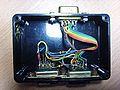
Y-box with 5 diodes (looks incomplete)
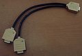
Joystick Y-cable

Schematic with 14 diodes (supports 3 buttons)

Schematic with 10 diodes (supports 1 button)

CPC Plus with 8 diodes (supports 0 buttons)

Y-cable for CPC from Lindy


